
Introductory Circuit Analysis (13th Edition)
13th Edition
ISBN: 9780133923605
Author: Robert L. Boylestad
Publisher: PEARSON
expand_more
expand_more
format_list_bulleted
Related questions
Concept explainers
Question

Transcribed Image Text:**CO-8 Relay and CT Analysis**
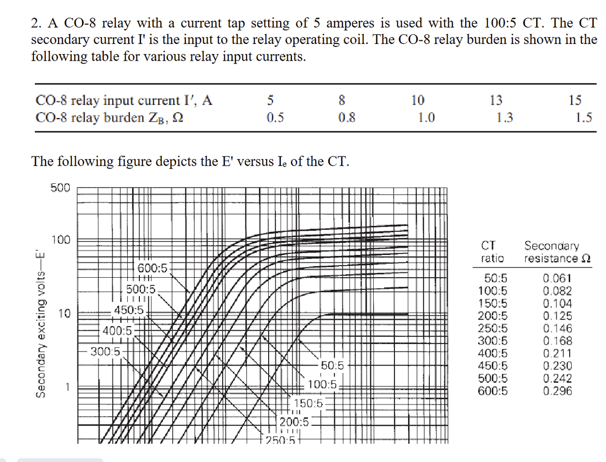
A CO-8 relay with a current tap setting of 5 amperes is used with a 100:5 current transformer (CT). The CT secondary current \( I' \) serves as the input to the relay operating coil. The CO-8 relay burden for various relay input currents is listed in the table below:
| **CO-8 relay input current \( I' \), A** | 5 | 8 | 10 | 13 | 15 |
|-----------------------------------------|----|----|----|----|----|
| **CO-8 relay burden \( Z_B, \, \Omega \)** | 0.5| 0.8| 1.0| 1.3| 1.5|
The graph represents the relationship between the secondary exciting voltage \( E' \) and the exciting current \( I_e \) for the CT.
**Graph Explanation:**
- **X-axis:** Represents the exciting current, \( I_e \).
- **Y-axis:** Represents the secondary exciting voltage, \( E' \).
- Multiple curves depict different CT ratios ranging from 50:5 to 600:5.
The table next to the graph provides the secondary resistance \( \Omega \) for each CT ratio:
| **CT ratio** | **Secondary resistance \( \Omega \)** |
|--------------|----------------------|
| 50:5 | 0.061 |
| 100:5 | 0.082 |
| 150:5 | 0.104 |
| 200:5 | 0.125 |
| 250:5 | 0.146 |
| 300:5 | 0.168 |
| 400:5 | 0.211 |
| 450:5 | 0.230 |
| 500:5 | 0.242 |
| 600:5 | 0.296 |
Understanding this graph and table is crucial for analyzing the performance and compatibility of CTs with different relay settings.

Transcribed Image Text:### Electrical Engineering Problem Analysis
#### Graph Explanation:
The graph presents the relationship between secondary exciting current (Iₑ) on a logarithmic x-axis and secondary voltage (V) on a logarithmic y-axis. Various lines represent different current transformer (CT) ratios, such as 100:5, 150:5, 200:5, etc.
#### Problem Statement:
1. **Primary Current Computation:**
- Compute the primary current for two scenarios:
- (a) \( I' = 10 \, \text{A} \) and \( Z_B = 1 \, \Omega \)
- (b) \( I' = 13 \, \text{A} \) and \( Z_B = 1.3 \, \Omega \)
2. **Plotting Task:**
- Plot \( I' \) versus \( I \) for five values of \( I' \) detailed in a provided table.
- Previously calculated primary currents for \( I' = 5, 8, \) and \( 15 \, \text{A} \) during Session 12 (October 2nd).
- Ensure the plot clearly shows the saturation region of the curve.
3. **Reliable Relay Operation:**
- For trustworthy relay operation, ensure the fault-to-pickup current ratio with minimum fault current exceeds two.
- Determine the minimum fault current for employing this CT and relay with a 5-A tap setting.
- In essence, calculate the minimum fault current necessary for the relay to trip reliably.
This exercise involves analyzing physical electrical principles associated with CTs and relay settings, requiring understanding of saturation curves and fault current calculations for effective power system protection.
Expert Solution
This question has been solved!
Explore an expertly crafted, step-by-step solution for a thorough understanding of key concepts.

This is a popular solution

Trending nowThis is a popular solution!

Step by stepSolved in 3 steps with 2 images

Knowledge Booster


Learn more about
Need a deep-dive on the concept behind this application? Look no further. Learn more about this topic, electrical-engineering and related others by exploring similar questions and additional content below.Similar questions
Recommended textbooks for you
- Introductory Circuit Analysis (13th Edition)Electrical EngineeringISBN:9780133923605Author:Robert L. BoylestadPublisher:PEARSON
 Delmar's Standard Textbook Of ElectricityElectrical EngineeringISBN:9781337900348Author:Stephen L. HermanPublisher:Cengage Learning
 Programmable Logic ControllersElectrical EngineeringISBN:9780073373843Author:Frank D. PetruzellaPublisher:McGraw-Hill Education
  Fundamentals of Electric CircuitsElectrical EngineeringISBN:9780078028229Author:Charles K Alexander, Matthew SadikuPublisher:McGraw-Hill Education
 Electric Circuits. (11th Edition)Electrical EngineeringISBN:9780134746968Author:James W. Nilsson, Susan RiedelPublisher:PEARSON
 Engineering ElectromagneticsElectrical EngineeringISBN:9780078028151Author:Hayt, William H. (william Hart), Jr, BUCK, John A.Publisher:Mcgraw-hill Education,
Introductory Circuit Analysis (13th Edition)
Electrical Engineering
ISBN:9780133923605
Author:Robert L. Boylestad
Publisher:PEARSON
Delmar's Standard Textbook Of Electricity
Electrical Engineering
ISBN:9781337900348
Author:Stephen L. Herman
Publisher:Cengage Learning
Programmable Logic Controllers
Electrical Engineering
ISBN:9780073373843
Author:Frank D. Petruzella
Publisher:McGraw-Hill Education
Fundamentals of Electric Circuits
Electrical Engineering
ISBN:9780078028229
Author:Charles K Alexander, Matthew Sadiku
Publisher:McGraw-Hill Education
Electric Circuits. (11th Edition)
Electrical Engineering
ISBN:9780134746968
Author:James W. Nilsson, Susan Riedel
Publisher:PEARSON
Engineering Electromagnetics
Electrical Engineering
ISBN:9780078028151
Author:Hayt, William H. (william Hart), Jr, BUCK, John A.
Publisher:Mcgraw-hill Education,