Principles of Heat Transfer (Activate Learning with these NEW titles from Engineering!)
8th Edition
ISBN: 9781305387102
Author: Kreith, Frank; Manglik, Raj M.
Publisher: Cengage Learning
expand_more
expand_more
format_list_bulleted
Topic Video
Question
Show complete and correct solution, thank you.

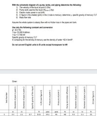
Transcribed Image Text:With the schematic diagram of a pump, tanks, and piping determine the following:
1) The velocity of the liquid at point 2 (ft/s)
2) Pump work used by the liquid (Wpump U) (hp)
3) Electric motor power in out (kVW)
4) In figure 3, the shaded (pink) in the U tube is mercury; determine y. specific gravity of mercury 13.7
5) Mass flow rate
Assume the whole system is steady flow with no friction loss in the pipes and tank.
Use only the following constant and conversion
g= 32.2 ft/s
1 hp= 33,000 ft-Ibf/min
1 hp = 0.746 kW
Specific gracity of mercury 13.7
In computing for the density of mercury use the density of water =62.4 lbm/ft³
Do not convert English units to SI units except horsepower to kW
Given:
in
in
ft
psia
psia
in
in
ft
1
3.1
2.1
0.7
0.51
14.1
45
60
4.1
2.1
25
Seat Number
Diameter of pipe in point 1
Diameter of pipe in point 2
Specific gravity of the liquid
h (ft) (see figure 2)
Pressure at point 1
Pressure at point 2
Pump and motor efficiency
Diameter of pipe in point 4
Diameter of pipe in point 5
Z3 (see figure 1)

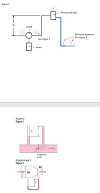
Transcribed Image Text:Figure 1
Pressurized tank
Z3
pump
Different diameters
See figure 3
See figure 2
motor
At point 2
Figure 2
V1
Stagnation
point
At points 4 and 5
Figure 3
D5
D4
y
Expert Solution
arrow_forward
Step 1
“Since you have posted a question with multiple sub-parts, we will solve first three subparts for you. To get remaining sub-part solved please repost the complete question and mention the sub-parts to be solved.”
Given Data:
Diameter of pipe at point 1
Diameter of pipe at point 2
The specific gravity of the liquid
Difference between the height of liquid in both pipe
Pressure at point 1
Pressure at point 2
Head at point 3
Efficiency of pump and motor
Step by stepSolved in 3 steps

Knowledge Booster
Learn more about
Need a deep-dive on the concept behind this application? Look no further. Learn more about this topic, mechanical-engineering and related others by exploring similar questions and additional content below.Similar questions
- Problems 5-117 through 5-122 Figures P5-117 through P5–122 show completed bending moment diagrams for beams. Develop the shearing force dia- gram and the loading diagram for each beamarrow_forwardHere are these questions if I could get help with themIf a spherical storage tank holds 40,000 gallons (120,000 liters) of water,what diameter must it have?If a cylindrical storage tank has a 40-foot (12 m) diameter circular 05::=how high must it be to hold 1 million gallons (3 million liters)?If water is moving at a rate of 3.2 ft3/sec (90,000 cc/sec), how manygallons (liters) per minute is this?If the specific gravity of gold is 19.0. what is the weight of a cubic inch(cubic centimeter) of gold? A cubic foot (cubic meter)?arrow_forwardStatics Problem !!! Help me Part A and Part B!!!! Answer it this Problem Correctly!! Please give correct Solutionarrow_forward
- The cylinder in Fig . 2-11 is used to raise the weight 9 in. If the bore of the cylinder is21/2 in. and the pressure is 1800 lbf/in.", how much work is accomplished?arrow_forwardFluid mechanics, i need solutions in 10 minutes please. MCQ/When a 4 lb weight is placed on the end of a floating wooden beam, the beam tilts at an angle θ= 2.1º with its upper right corner at the surface, as shown in the figure. The floating wooden beam having the dimensions of 8 in x 8 in x 10 ft. What is the buoyant force in 1b? A-230.132 lb B-171.965 lb C-149.002 lb D-233.761 lb E-179.235 lb F-164.682 lb G-186.519 lb H- 222.865 lb I-215.600 lb J-201.063 lb K-237.395 lb L-208.331 lb M-157.401 lb N-193.785 lbarrow_forwardIf solving the question in 3D calculations is difficult, then use the 2D system to determine the equations of the filuid pressure. Select one: O True O False A beaker is filled with a liquid of density p1 up to a certain height. A is a point, h m downwards from the free surface of the liquid as shown. The liquid is replaced by equal volume of another liquid of density p2. If p1 > p2, how will the pressure at point A change? Free Surface Base a) remain same b) increase c) decrease d) become zero Select one: O A B O C D.arrow_forward
- Please help. Written on paper not typed on computer or keyboard please. Need help on all questions. Please include all units, steps to the problem and information such as its direction or if it is in compression or tension. Thx.arrow_forwardView Image. Show complete and detailed solution. Please write legibly. Answer: 64.3 degreesarrow_forwardFluidsarrow_forward
arrow_back_ios
SEE MORE QUESTIONS
arrow_forward_ios
Recommended textbooks for you
 Principles of Heat Transfer (Activate Learning wi...Mechanical EngineeringISBN:9781305387102Author:Kreith, Frank; Manglik, Raj M.Publisher:Cengage Learning
 International Edition---engineering Mechanics: St...Mechanical EngineeringISBN:9781305501607Author:Andrew Pytel And Jaan KiusalaasPublisher:CENGAGE L

Principles of Heat Transfer (Activate Learning wi...
Mechanical Engineering
ISBN:9781305387102
Author:Kreith, Frank; Manglik, Raj M.
Publisher:Cengage Learning

International Edition---engineering Mechanics: St...
Mechanical Engineering
ISBN:9781305501607
Author:Andrew Pytel And Jaan Kiusalaas
Publisher:CENGAGE L