
Structural Analysis
6th Edition
ISBN: 9781337630931
Author: KASSIMALI, Aslam.
Publisher: Cengage,
expand_more
expand_more
format_list_bulleted
Related questions
Question
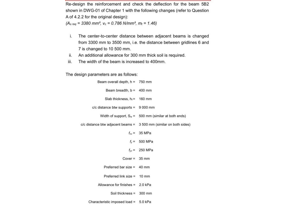

Transcribed Image Text:Re-design the reinforcement and check the deflection for the beam 5B2
shown in DWG-01 of Chapter 1 with the following changes (refer to Question
A of 4.2.2 for the original design):
(As req = 3380 mm?, vc = 0.786 N/mm?, m = 1.46)
i.
The center-to-center distance between adjacent beams is changed
from 3300 mm to 3500 mm, i.e. the distance between gridlines 6 and
7 is changed to 10 500 mm.
i.
An additional allowance for 300 mm thick soil is required.
i.
The width of the beam is increased to 400mm.
The design parameters are as follows:
Beam overall depth, h =
750 mm
Beam breadth, b =
400 mm
Slab thickness, h =
160 mm
c/c distance btw supports =
9 000 mm
Width of support, Sw =
500 mm (similar at both ends)
c/c distance btw adjacent beams =
3 500 mm (similar on both sides)
feu = 35 MPa
fy = 500 MPa
fyy = 250 MPa
Cover =
35 mm
Preferred bar size =
40 mm
Preferred link size =
10 mm
Allowance for finishes =
2.0 kPa
Soil thickness =
300 mm
Characteristic imposed load =
5.0 kPa
Expert Solution
This question has been solved!
Explore an expertly crafted, step-by-step solution for a thorough understanding of key concepts.

Step by stepSolved in 5 steps

Knowledge Booster


Learn more about
Need a deep-dive on the concept behind this application? Look no further. Learn more about this topic, civil-engineering and related others by exploring similar questions and additional content below.Similar questions
- 609arrow_forward04. The load Q is gradually increased from zero to 120kN. a) Does failure occur in bars BE and BD? b) Determine the maximum deflection at pointB. a = 0.64m Square Cross-Section 10mm x 10mm 1.7m E A36-Carbon Steel A36-Carbon Steel 2.64 m OD for all pins = 6mmarrow_forwardPlease show all stepsarrow_forward
- Big and clear handwriting with the drawing please. Make sure calculations and answers are accurate please. THANK YOUarrow_forwardRead the question carefully The W360 x 79 simply supported beam is made of A-36 steel and is subjected to the loadingshown. Using the superposition method, calculate (a) the Slope at A, (b) the maximum Deflection ofthe beam and at center.arrow_forwardI need answer typing clear urjent no chatgpt i will give10 upvotesarrow_forward
arrow_back_ios
arrow_forward_ios
Recommended textbooks for you
 Structural Analysis (10th Edition)Civil EngineeringISBN:9780134610672Author:Russell C. HibbelerPublisher:PEARSON
 Principles of Foundation Engineering (MindTap Cou...Civil EngineeringISBN:9781337705028Author:Braja M. Das, Nagaratnam SivakuganPublisher:Cengage Learning
 Fundamentals of Structural AnalysisCivil EngineeringISBN:9780073398006Author:Kenneth M. Leet Emeritus, Chia-Ming Uang, Joel LanningPublisher:McGraw-Hill Education
 Traffic and Highway EngineeringCivil EngineeringISBN:9781305156241Author:Garber, Nicholas J.Publisher:Cengage Learning
Structural Analysis (10th Edition)
Civil Engineering
ISBN:9780134610672
Author:Russell C. Hibbeler
Publisher:PEARSON
Principles of Foundation Engineering (MindTap Cou...
Civil Engineering
ISBN:9781337705028
Author:Braja M. Das, Nagaratnam Sivakugan
Publisher:Cengage Learning
Fundamentals of Structural Analysis
Civil Engineering
ISBN:9780073398006
Author:Kenneth M. Leet Emeritus, Chia-Ming Uang, Joel Lanning
Publisher:McGraw-Hill Education
Traffic and Highway Engineering
Civil Engineering
ISBN:9781305156241
Author:Garber, Nicholas J.
Publisher:Cengage Learning