
Introductory Circuit Analysis (13th Edition)
13th Edition
ISBN: 9780133923605
Author: Robert L. Boylestad
Publisher: PEARSON
expand_more
expand_more
format_list_bulleted
Related questions
Question
I need help understanding part B. See attached photo.
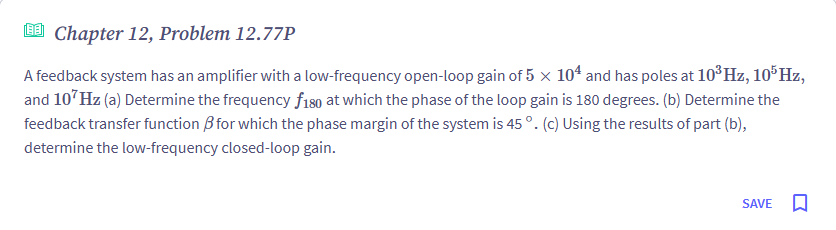

Transcribed Image Text:Chapter 12, Problem 12.77P
A feedback system has an amplifier with a low-frequency open-loop gain of 5 × 10⁴ and has poles at 103 Hz, 105 Hz,
and 107Hz (a) Determine the frequency f180 at which the phase of the loop gain is 180 degrees. (b) Determine the
feedback transfer function ẞ for which the phase margin of the system is 45°. (c) Using the results of part (b),
determine the low-frequency closed-loop gain.
SAVE ☐
Expert Solution
This question has been solved!
Explore an expertly crafted, step-by-step solution for a thorough understanding of key concepts.

Step by stepSolved in 2 steps

Knowledge Booster

Similar questions
- I am having trouble understanding part B. see attached photoarrow_forwardConsider the following feedback amplifier circuit. Assume lambda= 0, VDD RD2 R01 VinM₁ M₂ -Vout Select one: O a. none of these R₂ the open loop input resistance RinoL and the closed loop input resistances RincLare respectively: O b. RinoL = 1/gm and RincL= 1/gm(1+kA1) O C. RinoL = ∞o and Rincl= (1+ KA1) d. RinoLand RinCL = 00arrow_forwardI need the answer as soon as possiblearrow_forward
- Question 666 electric Full explain this question very fastarrow_forwardK The open loop transfer function of unity feedback system is By what factor the gain (K) should s(Ts+1) be multiplied so that the damping ratio is increased from 0.2 to 0.8?arrow_forwardAn uncompensated system shown in Figure 3(a) has forward transfer function G(s) with a unity feedback. a. Design a phase lead compensator shown in Figure 3(b) cascaded with the uncompensated system shown in Figure 3(a) that will have a 40% or better improvement of the settling time, at least 3 times improvement in percent overshoot. Assume a compensator zero at (given value zc = -10).Show all the complete solution.arrow_forward
- 8. For the collector feedback configuration, determine : +16 V (a IB (b) Ic () Vc 3.6 kQ 470 k2 Vc IB B = 120 0.51 k2arrow_forwardGiven the feedback circuit below and assuming the voltage amplifier has gain A₂, input resistance R₁ and output resistance Ro, answer the following questions: + a. Loop gain b. Closed loop gain Re C. Input resistance d. Output resistance Rin м + RE A) Sketch the feedback small signal model of this circuit. (Hint: You may convert the input VIN and source resistance Rs to its Norton current equivalent if needed) B) Find the following in terms of the amplifier parameters and resistances R, and RF: Routarrow_forward(a) Identify the correct answers 1. Virtual ground of an OP-AMP (a) Is formed only with negative feedback (b) Is always an AC ground, may occasionally be a DC ground (for PMOS) (c) Is coined as a terminology where the input signal splits equally between the terminals (d) Leads to the concept of almost zero difference between the two inputs (both DC and AC) using feedback 2. In an OP-AMP based circuit (a) Phase margin of the closed loop transfer function is a measure of stable operation (b) 45° is a desirable phase margin as it balances the frequency domain stability and the time domain settling optimally (c) Absolute open loop gain numbers are not that important, as long as they are large (d) 45° is only achieved when the RHP zero is placed on one of the poles 3. In a differential amplifier biased with a given tail current I, to increase the overdrive voltage by 2X without changing input capacitive loading, we should (a) Increase W by 2X and reduce L by 2X (b) Reduce W by 2X and…arrow_forward
- Need Help on #1.5 part (a)arrow_forwardUsing any number of Op-Amps, design multistage amplifier to amplify input Ac signal with 0.01V amplitude, the expected output voltage would have 4V amplitude. The input signal frequency = 10 KHz. Assume gain bandwidth product of Op-Amp = 1 MHzarrow_forwardplease do question 2 and 3arrow_forward
arrow_back_ios
SEE MORE QUESTIONS
arrow_forward_ios
Recommended textbooks for you
- Introductory Circuit Analysis (13th Edition)Electrical EngineeringISBN:9780133923605Author:Robert L. BoylestadPublisher:PEARSON
 Delmar's Standard Textbook Of ElectricityElectrical EngineeringISBN:9781337900348Author:Stephen L. HermanPublisher:Cengage Learning
 Programmable Logic ControllersElectrical EngineeringISBN:9780073373843Author:Frank D. PetruzellaPublisher:McGraw-Hill Education
  Fundamentals of Electric CircuitsElectrical EngineeringISBN:9780078028229Author:Charles K Alexander, Matthew SadikuPublisher:McGraw-Hill Education
 Electric Circuits. (11th Edition)Electrical EngineeringISBN:9780134746968Author:James W. Nilsson, Susan RiedelPublisher:PEARSON
 Engineering ElectromagneticsElectrical EngineeringISBN:9780078028151Author:Hayt, William H. (william Hart), Jr, BUCK, John A.Publisher:Mcgraw-hill Education,
Introductory Circuit Analysis (13th Edition)
Electrical Engineering
ISBN:9780133923605
Author:Robert L. Boylestad
Publisher:PEARSON
Delmar's Standard Textbook Of Electricity
Electrical Engineering
ISBN:9781337900348
Author:Stephen L. Herman
Publisher:Cengage Learning
Programmable Logic Controllers
Electrical Engineering
ISBN:9780073373843
Author:Frank D. Petruzella
Publisher:McGraw-Hill Education
Fundamentals of Electric Circuits
Electrical Engineering
ISBN:9780078028229
Author:Charles K Alexander, Matthew Sadiku
Publisher:McGraw-Hill Education
Electric Circuits. (11th Edition)
Electrical Engineering
ISBN:9780134746968
Author:James W. Nilsson, Susan Riedel
Publisher:PEARSON
Engineering Electromagnetics
Electrical Engineering
ISBN:9780078028151
Author:Hayt, William H. (william Hart), Jr, BUCK, John A.
Publisher:Mcgraw-hill Education,