Introductory Circuit Analysis (13th Edition)
13th Edition
ISBN: 9780133923605
Author: Robert L. Boylestad
Publisher: PEARSON
expand_more
expand_more
format_list_bulleted
Concept explainers
Question
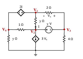
Can you find V1, V2, V3 and V4 with node analysis WITHOUT USING SUPERNODE TECHNIQUE.
y value is 4.( NEED only handwritten solution please otherwise downvote).

Transcribed Image Text:V4
yΩ
21
1+
1Ω
ww
V₁
V2
Hli
-
ΨΩ
Ι
2 Ω
3V
V +
Vx
YV
+ 1
V3
4Ω
Expert Solution
This question has been solved!
Explore an expertly crafted, step-by-step solution for a thorough understanding of key concepts.
This is a popular solution
Trending nowThis is a popular solution!
Step by stepSolved in 3 steps with 5 images

Knowledge Booster
Learn more about
Need a deep-dive on the concept behind this application? Look no further. Learn more about this topic, electrical-engineering and related others by exploring similar questions and additional content below.Similar questions
- The manimum value of the altenating wotaye and curent are 400 U and 20A respectvely s a cieritoanected to a svita supply . The ristantanerus values of the veltnge and current are 283V and 10 A respectvely of fime t=0, beth icreasing pesitively. 4) Write dan the gapressom for vwltaga and curend at pmet. b). Defermaned tha prver omsumed in the cranit. Take the velye and cunent to be ginusrida). fie P= VI end\ P = YI (PF)arrow_forwardA three way intersection is in need of a traffic signal control system and you have been assigned thetask to design and implement the system. Each direction has only one lane and one set of signalcontrol lights (green, yellow and red). Your design should only allow one go or green light at atime. Further, all transitions from green to red should go through an intermediate 2-4 secondsyellow light. and draw the design of the schematicarrow_forwardл-pad attenuators are commonly used in radio frequency and microwave transmission lines and can be balanced or unbalanced designs. The unbalanced attenuator shown in figure 2 below is supplied by two DC sources, one at each end. You have been asked to calculate the current through R3 and R5 using the Superposition Theorem and the appropriate set of values from table 1 below. Show step by step working out. 5 R1 R2 50V 5 R5 R3 ㅋ Fig 2 7 R4 4 R6 30Varrow_forward
arrow_back_ios
arrow_forward_ios
Recommended textbooks for you
 Introductory Circuit Analysis (13th Edition)Electrical EngineeringISBN:9780133923605Author:Robert L. BoylestadPublisher:PEARSON
 Delmar's Standard Textbook Of ElectricityElectrical EngineeringISBN:9781337900348Author:Stephen L. HermanPublisher:Cengage Learning
 Programmable Logic ControllersElectrical EngineeringISBN:9780073373843Author:Frank D. PetruzellaPublisher:McGraw-Hill Education
 Fundamentals of Electric CircuitsElectrical EngineeringISBN:9780078028229Author:Charles K Alexander, Matthew SadikuPublisher:McGraw-Hill Education
 Electric Circuits. (11th Edition)Electrical EngineeringISBN:9780134746968Author:James W. Nilsson, Susan RiedelPublisher:PEARSON
 Engineering ElectromagneticsElectrical EngineeringISBN:9780078028151Author:Hayt, William H. (william Hart), Jr, BUCK, John A.Publisher:Mcgraw-hill Education,

Introductory Circuit Analysis (13th Edition)
Electrical Engineering
ISBN:9780133923605
Author:Robert L. Boylestad
Publisher:PEARSON

Delmar's Standard Textbook Of Electricity
Electrical Engineering
ISBN:9781337900348
Author:Stephen L. Herman
Publisher:Cengage Learning

Programmable Logic Controllers
Electrical Engineering
ISBN:9780073373843
Author:Frank D. Petruzella
Publisher:McGraw-Hill Education

Fundamentals of Electric Circuits
Electrical Engineering
ISBN:9780078028229
Author:Charles K Alexander, Matthew Sadiku
Publisher:McGraw-Hill Education

Electric Circuits. (11th Edition)
Electrical Engineering
ISBN:9780134746968
Author:James W. Nilsson, Susan Riedel
Publisher:PEARSON

Engineering Electromagnetics
Electrical Engineering
ISBN:9780078028151
Author:Hayt, William H. (william Hart), Jr, BUCK, John A.
Publisher:Mcgraw-hill Education,