
Introductory Circuit Analysis (13th Edition)
13th Edition
ISBN: 9780133923605
Author: Robert L. Boylestad
Publisher: PEARSON
expand_more
expand_more
format_list_bulleted
Related questions
Question
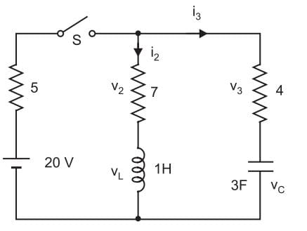

Transcribed Image Text:www
S
20 V
V2
*wim
7
1H
13
V3
www.
3F VC

Transcribed Image Text:Calculate the values of i2, 13, V2, V3,Vc and v₁ in the network shown in Fig.
at the following times :
(i) At time, t = 0 immediately after the switch S is
closed.
(ii) At time, t→∞o i.e. in the steady state. All resistances
are in ohms.
Expert Solution
This question has been solved!
Explore an expertly crafted, step-by-step solution for a thorough understanding of key concepts.

Step by stepSolved in 3 steps

Knowledge Booster


Learn more about
Need a deep-dive on the concept behind this application? Look no further. Learn more about this topic, electrical-engineering and related others by exploring similar questions and additional content below.Similar questions
- Problems: 1. In the circuit shown in the figure, R, = R2 = 2kn, C = 500µF, C2 = 1000µF, C3 = 1000µF, and e = 50V. Capacitors have no charge at t-0 when switch S is set to position A. R1 R2 a) Find the current through the power supply at t-0. b) Find the time constant of the circuit. c) When the capacitors are fully charged, find the potential difference between the plates of C2. R = 100 R2 = 40N 2. For the circuit with the known values of its elements indicated in the figure and I3=0.2 A, a) find R3 and b) calculate I and I2. & = 6V R3 Ez = 12V 13 3. A point charge q with mass m moving with a velocity of i = vî enters a uniform magnetic field expressed as B = B,î + B,j + B,k. a) Find the magnetic force acting on the point charge. b) Find the radius and pitch of the spiral trajectory of the point charge.arrow_forwardGuide for all parts please, please show work for understanding, thank you :)arrow_forwardThe switch in the circuit below closes at time t=0, and a long time passes such that steady-state conditions are reached. Given the following parameters, determine the voltage across the resistor R3. V t=0 R1 R2 ww R3 In this question, V = 15, R1 = 44Q, R2 = = 610, R3 = 510, L = 31mH, and C = 535nF.arrow_forward
- Consider the circuit below with V = 20 V and R1 = 8 ohms, R2 = 10 ohms, and C1 = 15 mF. There is no energy stored by the capacitor 1: Find the steady state voltage across and current through the capacitor. 2: Find the time constant for the circuit. 3: Find the expression for the voltage across the capacitor as a function of time.arrow_forward2. An aging battery generating 200e-5t volts is connected in series with a 20 ohm resistor, and a 0.01 farad capacitor. Assuming q = 0 at t = 0, find the charge and current for all t > 0. Show that the charge reaches a maximum and find the time it is reached. 3. In an arbitrary RC circuit with constant emf E, use the method of sepa- ration of variables to derive the formula Q(t) = Ae-t/RC + EC for the charge on the capacitor, where A is an arbitrary constant. If Q(0) = Qo, what is A? CS Scanned with CamScannerarrow_forwardThe switch in the circuit below closes at time t=0, and a long time passes such that steady-state conditions are reached. Given the following parameters, determine the voltage across the resistor R3. t=0 R1 R2 R3 In this question, V = 10.3, R1 = 570, R2 = 760, R3 = 570, L = 29mH, and C= 142nF.arrow_forward
arrow_back_ios
arrow_forward_ios
Recommended textbooks for you
- Introductory Circuit Analysis (13th Edition)Electrical EngineeringISBN:9780133923605Author:Robert L. BoylestadPublisher:PEARSON
 Delmar's Standard Textbook Of ElectricityElectrical EngineeringISBN:9781337900348Author:Stephen L. HermanPublisher:Cengage Learning
 Programmable Logic ControllersElectrical EngineeringISBN:9780073373843Author:Frank D. PetruzellaPublisher:McGraw-Hill Education
  Fundamentals of Electric CircuitsElectrical EngineeringISBN:9780078028229Author:Charles K Alexander, Matthew SadikuPublisher:McGraw-Hill Education
 Electric Circuits. (11th Edition)Electrical EngineeringISBN:9780134746968Author:James W. Nilsson, Susan RiedelPublisher:PEARSON
 Engineering ElectromagneticsElectrical EngineeringISBN:9780078028151Author:Hayt, William H. (william Hart), Jr, BUCK, John A.Publisher:Mcgraw-hill Education,
Introductory Circuit Analysis (13th Edition)
Electrical Engineering
ISBN:9780133923605
Author:Robert L. Boylestad
Publisher:PEARSON
Delmar's Standard Textbook Of Electricity
Electrical Engineering
ISBN:9781337900348
Author:Stephen L. Herman
Publisher:Cengage Learning
Programmable Logic Controllers
Electrical Engineering
ISBN:9780073373843
Author:Frank D. Petruzella
Publisher:McGraw-Hill Education
Fundamentals of Electric Circuits
Electrical Engineering
ISBN:9780078028229
Author:Charles K Alexander, Matthew Sadiku
Publisher:McGraw-Hill Education
Electric Circuits. (11th Edition)
Electrical Engineering
ISBN:9780134746968
Author:James W. Nilsson, Susan Riedel
Publisher:PEARSON
Engineering Electromagnetics
Electrical Engineering
ISBN:9780078028151
Author:Hayt, William H. (william Hart), Jr, BUCK, John A.
Publisher:Mcgraw-hill Education,