Introductory Circuit Analysis (13th Edition)
13th Edition
ISBN: 9780133923605
Author: Robert L. Boylestad
Publisher: PEARSON
expand_more
expand_more
format_list_bulleted
Question
thumb_up100%
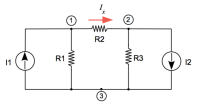
Calculate the power absorbed by the resistor R2. Adjust the resistor such a
way that the network delivers maximum power to the load resistor R2 = 10W. R1 =
5W , R3 = 3W. The network is supplied with two current sources; I1 = 10A and I2 = 2A

Expert Solution
This question has been solved!
Explore an expertly crafted, step-by-step solution for a thorough understanding of key concepts.
This is a popular solution
Trending nowThis is a popular solution!
Step by stepSolved in 3 steps with 3 images

Knowledge Booster
Learn more about
Need a deep-dive on the concept behind this application? Look no further. Learn more about this topic, electrical-engineering and related others by exploring similar questions and additional content below.Similar questions
- (a) Can a voltage be negative? Explain. (b) Figure 1 shows a source transformation where a voltage source is transform to a current source. What are the values of the resistor R₁ and current / in the current source in terms of the voltage source? Ꭱ R₁ voltage source Figure 1 current source (c) Find the total resistance Rε for the circuit shown in figure 2. RE 6002 4052 ww 1002 902. Figure 2 (d) Find V, and I₁ in the circuit of figure 3, your answer should include the equations used to obtain the voltage and the current. 16 Ω + + 24 V 4 V₁ 0.5 11 42 V₁ Figure 3arrow_forwardFind the total resistance if R1 = 200 ohms and R2 = 200 and R3 = 800 ohms are all connected in series.arrow_forward3. The resistances in the circuit below are in Ohms. Use voltage division to calculate the voltages V1 and V2. Then determine the voltage V (reference polarity marked in red font.) 9V 5.0 6 2 V1 V 12 V2arrow_forward
- Hi could someone please help me with the following question I am given the following information. The variable resistor Ro in the circuit in (Figure 1) is adjusted for maximum power transfer to Ro. Suppose that v1 = 240 V, and v2 = 140 V a)Find the value of Ro (I found this to be 2.5 Ohms which was correct but I can not do the rest of the parts to this question) b) Find the maximum power that can be delivered to Ro c)What percentage of the total power developed in the circuit is delivered to Ro found in part A? d) (this part is included in the images) Thanks so much!arrow_forwardKindly answer this problem.Thanks a lot.arrow_forward1. According to KVL, the voltage supplied to a closed circuit is equal to: A. The sum of the resistances in the circuit B. OV C. The power dropped across the loads in the circuit D. The sum of the voltage drops across the loads 2. Which of the following is NOT a true statement regarding Kirchhoff's Voltage Law? A. It helps us determine unknown values at desired points in a circuit B. It is often used in combination with Ohm's Law C. It states that zero voltage can be dropped in a circuit D. It is based on the principle of the conservation of energy 3. Two circuit elements are in series when: A. They have only one common terminal B. They are connected in alphabetical order C. They have more than one common terminal D. They have the same voltage drop 4. True or false: Current is the same through all points in a series circuit. A. True B. False 5. A voltage divider receives an input voltage of 9V. If the two series resistors in the divider have the same resistance, what will the output…arrow_forward
arrow_back_ios
arrow_forward_ios
Recommended textbooks for you
 Introductory Circuit Analysis (13th Edition)Electrical EngineeringISBN:9780133923605Author:Robert L. BoylestadPublisher:PEARSON
 Delmar's Standard Textbook Of ElectricityElectrical EngineeringISBN:9781337900348Author:Stephen L. HermanPublisher:Cengage Learning
 Programmable Logic ControllersElectrical EngineeringISBN:9780073373843Author:Frank D. PetruzellaPublisher:McGraw-Hill Education
 Fundamentals of Electric CircuitsElectrical EngineeringISBN:9780078028229Author:Charles K Alexander, Matthew SadikuPublisher:McGraw-Hill Education
 Electric Circuits. (11th Edition)Electrical EngineeringISBN:9780134746968Author:James W. Nilsson, Susan RiedelPublisher:PEARSON
 Engineering ElectromagneticsElectrical EngineeringISBN:9780078028151Author:Hayt, William H. (william Hart), Jr, BUCK, John A.Publisher:Mcgraw-hill Education,

Introductory Circuit Analysis (13th Edition)
Electrical Engineering
ISBN:9780133923605
Author:Robert L. Boylestad
Publisher:PEARSON

Delmar's Standard Textbook Of Electricity
Electrical Engineering
ISBN:9781337900348
Author:Stephen L. Herman
Publisher:Cengage Learning

Programmable Logic Controllers
Electrical Engineering
ISBN:9780073373843
Author:Frank D. Petruzella
Publisher:McGraw-Hill Education

Fundamentals of Electric Circuits
Electrical Engineering
ISBN:9780078028229
Author:Charles K Alexander, Matthew Sadiku
Publisher:McGraw-Hill Education

Electric Circuits. (11th Edition)
Electrical Engineering
ISBN:9780134746968
Author:James W. Nilsson, Susan Riedel
Publisher:PEARSON

Engineering Electromagnetics
Electrical Engineering
ISBN:9780078028151
Author:Hayt, William H. (william Hart), Jr, BUCK, John A.
Publisher:Mcgraw-hill Education,