Introductory Circuit Analysis (13th Edition)
13th Edition
ISBN: 9780133923605
Author: Robert L. Boylestad
Publisher: PEARSON
expand_more
expand_more
format_list_bulleted
Question

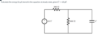
Transcribed Image Text:Calculate the energy (in µJ) stored in the capacitor at steady-state, given C = 6.8 µF.
200 Ω
10 V
ww
• 800 Ω
Expert Solution
This question has been solved!
Explore an expertly crafted, step-by-step solution for a thorough understanding of key concepts.
Step by stepSolved in 3 steps

Knowledge Booster
Learn more about
Need a deep-dive on the concept behind this application? Look no further. Learn more about this topic, electrical-engineering and related others by exploring similar questions and additional content below.Similar questions
- A 400 Hz sinusoidal voltage with a maximum amplitude of 120 V at t = 0 is applied across the terminals of an inductor. The maximum amplitude of the steady-state current in the inductor is 20 A Part A What is the frequency of the inductor current? Express your answer with the appropriate units. f= Part B Submit Request Answer μÀ 0₁ = Value Submit If the phase angle of the voltage is zero, what is the phase angle of the current? Express your answer with the appropriate units. μA Value Units Request Answer ? Units ?arrow_forward10. Initially, the capacitors in the circuit in the given figure are uncharged. Determine the capacitor voltage after the given times: 30V + a. 15 ms b. 30 ms c. 45 ms d. 60 ms e. 75 ms R M 150 100μFarrow_forwardDescription: Inductance Capacitors and inductors, have a different type of AC resistance known as reactance, ( XL, XC ). Reactance also impedes the flow of current, but the amount of reactance is not a fixed quantity for one inductor or capacitor The reactance value of an inductor or a capacitor depends upon the frequency of the supply current as well as on the DC value of the component itself. Measurements Frequency (Hz) Z I VR=I*R VL=I* 10 60V 50 50V 100 20V Evaluation: Determine the total current in the circuit I by using Determine using the formula Determine the impedance by using the form Determine the phase difference between and Observe the waveforms and attach the print screen of the Ouput(CRO Output). What do you observe from the Output Waveforms. Repeat for different values in the table.arrow_forward
Recommended textbooks for you
 Introductory Circuit Analysis (13th Edition)Electrical EngineeringISBN:9780133923605Author:Robert L. BoylestadPublisher:PEARSON
 Delmar's Standard Textbook Of ElectricityElectrical EngineeringISBN:9781337900348Author:Stephen L. HermanPublisher:Cengage Learning
 Programmable Logic ControllersElectrical EngineeringISBN:9780073373843Author:Frank D. PetruzellaPublisher:McGraw-Hill Education
 Fundamentals of Electric CircuitsElectrical EngineeringISBN:9780078028229Author:Charles K Alexander, Matthew SadikuPublisher:McGraw-Hill Education
 Electric Circuits. (11th Edition)Electrical EngineeringISBN:9780134746968Author:James W. Nilsson, Susan RiedelPublisher:PEARSON
 Engineering ElectromagneticsElectrical EngineeringISBN:9780078028151Author:Hayt, William H. (william Hart), Jr, BUCK, John A.Publisher:Mcgraw-hill Education,

Introductory Circuit Analysis (13th Edition)
Electrical Engineering
ISBN:9780133923605
Author:Robert L. Boylestad
Publisher:PEARSON

Delmar's Standard Textbook Of Electricity
Electrical Engineering
ISBN:9781337900348
Author:Stephen L. Herman
Publisher:Cengage Learning

Programmable Logic Controllers
Electrical Engineering
ISBN:9780073373843
Author:Frank D. Petruzella
Publisher:McGraw-Hill Education

Fundamentals of Electric Circuits
Electrical Engineering
ISBN:9780078028229
Author:Charles K Alexander, Matthew Sadiku
Publisher:McGraw-Hill Education

Electric Circuits. (11th Edition)
Electrical Engineering
ISBN:9780134746968
Author:James W. Nilsson, Susan Riedel
Publisher:PEARSON

Engineering Electromagnetics
Electrical Engineering
ISBN:9780078028151
Author:Hayt, William H. (william Hart), Jr, BUCK, John A.
Publisher:Mcgraw-hill Education,