
Introductory Circuit Analysis (13th Edition)
13th Edition
ISBN: 9780133923605
Author: Robert L. Boylestad
Publisher: PEARSON
expand_more
expand_more
format_list_bulleted
Related questions
Question
thumb_up100%
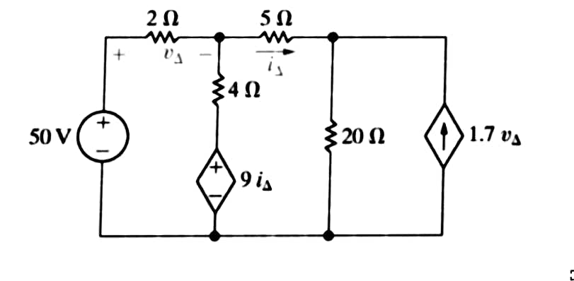
Calculate i∆ and v∆. Show all work please!
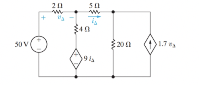

Transcribed Image Text:The image features an electrical circuit diagram comprising various components:
1. **Voltage Source**: The circuit is powered by a 50 V voltage source, located on the left side.
2. **Resistors**:
- A 2-ohm (Ω) resistor in series with the voltage source.
- A 4-ohm resistor in series with a dependent current source represented as \(9i_\Delta\).
- A 5-ohm resistor in the upper branch, through which the current \(i_\Delta\) flows.
- A 20-ohm resistor in parallel with the dependent voltage source (next to the 4-ohm resistor).
3. **Dependent Sources**:
- A current-dependent current source \(9i_\Delta\) is in parallel with the 4-ohm resistor.
- A voltage-dependent current source with a value of \(1.7v_\Delta\) is in parallel with the 20-ohm resistor.
4. **Node Voltages and Currents**:
- The voltage across the 2-ohm resistor is labeled as \(v_\Delta\).
- The current through the 5-ohm resistor is labeled \(i_\Delta\), with direction marked by a rightward arrow.
The circuit illustrates the interaction between independent components (like the voltage source and resistors) and dependent sources, which adjust their output based on other parameters in the circuit, such as current or voltage through specific elements.
Expert Solution
arrow_forward
Step 1: Determination of given parameters,
The circuit diagram,

Step by stepSolved in 4 steps with 11 images

Knowledge Booster

Similar questions
- Plot the dc bias line for this circuit. www11 R₁ 1.5 ΜΩ R₂ 1.5 ΜΩ VGS (V) +30 V RD 1.1 ΚΩ 2N5459 www11 Rs 10 ΚΩ Minimum and maximum curves are from the datasheets. ID (mA) 16 -12 -10 Qmax 14 1 L L 1 -8 -6 -4 -2 12 10 8 6 4 Qmin Hó VG Rs 1 2 = 1.5 mA 4 1 6 8 10 12 14 16 18 VGarrow_forwardDraw Vout versus Vin for the given values below. Vin V₂ V₁ + V V V www 5 ΚΩ Vout Student numbers from 190207066 up to 200207084 V₁=5 V, V₂ 9 V, V₁= 15 V, V_= -15 V, V= 11 V, Output High =14 V Output Low = 11 V (including) Vin 13xSin tarrow_forwardPlease solve fast ,Have very less time. Do correctly . What is the total inductance in the circuit in Figure 13-1? A) 2600 uH B) 2100 mH C) 602 mH D) 800 mHarrow_forward
arrow_back_ios
arrow_forward_ios
Recommended textbooks for you
- Introductory Circuit Analysis (13th Edition)Electrical EngineeringISBN:9780133923605Author:Robert L. BoylestadPublisher:PEARSON
 Delmar's Standard Textbook Of ElectricityElectrical EngineeringISBN:9781337900348Author:Stephen L. HermanPublisher:Cengage Learning
 Programmable Logic ControllersElectrical EngineeringISBN:9780073373843Author:Frank D. PetruzellaPublisher:McGraw-Hill Education
  Fundamentals of Electric CircuitsElectrical EngineeringISBN:9780078028229Author:Charles K Alexander, Matthew SadikuPublisher:McGraw-Hill Education
 Electric Circuits. (11th Edition)Electrical EngineeringISBN:9780134746968Author:James W. Nilsson, Susan RiedelPublisher:PEARSON
 Engineering ElectromagneticsElectrical EngineeringISBN:9780078028151Author:Hayt, William H. (william Hart), Jr, BUCK, John A.Publisher:Mcgraw-hill Education,
Introductory Circuit Analysis (13th Edition)
Electrical Engineering
ISBN:9780133923605
Author:Robert L. Boylestad
Publisher:PEARSON
Delmar's Standard Textbook Of Electricity
Electrical Engineering
ISBN:9781337900348
Author:Stephen L. Herman
Publisher:Cengage Learning
Programmable Logic Controllers
Electrical Engineering
ISBN:9780073373843
Author:Frank D. Petruzella
Publisher:McGraw-Hill Education
Fundamentals of Electric Circuits
Electrical Engineering
ISBN:9780078028229
Author:Charles K Alexander, Matthew Sadiku
Publisher:McGraw-Hill Education
Electric Circuits. (11th Edition)
Electrical Engineering
ISBN:9780134746968
Author:James W. Nilsson, Susan Riedel
Publisher:PEARSON
Engineering Electromagnetics
Electrical Engineering
ISBN:9780078028151
Author:Hayt, William H. (william Hart), Jr, BUCK, John A.
Publisher:Mcgraw-hill Education,