
Systems Architecture
7th Edition
ISBN: 9781305080195
Author: Stephen D. Burd
Publisher: Cengage Learning
expand_more
expand_more
format_list_bulleted
Related questions
Question
Please can you develop a written solution from question (d) correctly! please help me understand.

Transcribed Image Text:(c)
(d)
discuss the test result data and possible faults if it fails this test.
comment on what manufacturers could do to implement quality management
systems, aiming to reduce failure rate and improve testability of electronic products.
marks)
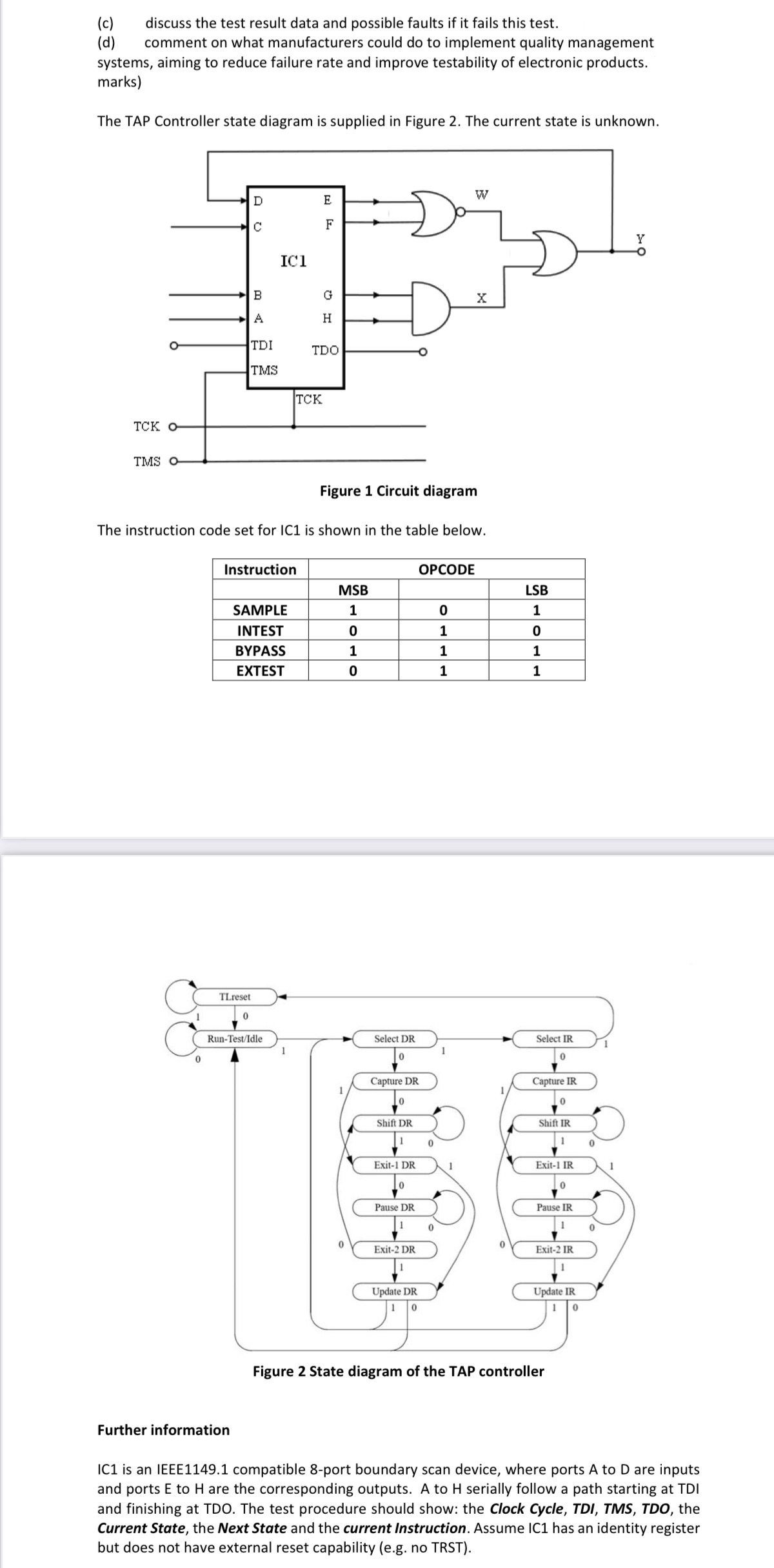
The TAP Controller state diagram is supplied in Figure 2. The current state is unknown.
тск о
TMS O
D
E
A O
с
IC1
F
B
A
G H
TDI
TDO
TMS
TCK
W
X
Figure 1 Circuit diagram
The instruction code set for IC1 is shown in the table below.
Instruction
OPCODE
MSB
LSB
SAMPLE
1
0
1
INTEST
0
1
0
BYPASS
1
1
1
EXTEST
0
1
1
0
TLreset
0
Run-Test/Idle
Y
1
Select DR
0
1
Select IR
0
Capture DR
Capture IR
0
0
Shift DR
Shift IR
0
0
Exit-1 DR
1
Exit-1 IR
1
0
0
Pause DR
Pause IR
1
0
0
0
Exit-2 DR
Exit-2 IR
Update DR
1 0
Update IR
0
Figure 2 State diagram of the TAP controller
Further information
IC1 is an IEEE1149.1 compatible 8-port boundary scan device, where ports A to D are inputs
and ports E to H are the corresponding outputs. A to H serially follow a path starting at TDI
and finishing at TDO. The test procedure should show: the Clock Cycle, TDI, TMS, TDO, the
Current State, the Next State and the current Instruction. Assume IC1 has an identity register
but does not have external reset capability (e.g. no TRST).

Transcribed Image Text:(c)
(d)
discuss the test result data and possible faults if it fails this test.
comment on what manufacturers could do to implement quality management
systems, aiming to reduce failure rate and improve testability of electronic products.
marks)
The TAP Controller state diagram is supplied in Figure 2. The current state is unknown.
тск о
TMS O
D
E
A O
с
IC1
F
B
A
G H
TDI
TDO
TMS
TCK
W
X
Figure 1 Circuit diagram
The instruction code set for IC1 is shown in the table below.
Instruction
OPCODE
MSB
LSB
SAMPLE
1
0
1
INTEST
0
1
0
BYPASS
1
1
1
EXTEST
0
1
1
0
TLreset
0
Run-Test/Idle
Y
1
Select DR
0
1
Select IR
0
Capture DR
Capture IR
0
0
Shift DR
Shift IR
0
0
Exit-1 DR
1
Exit-1 IR
1
0
0
Pause DR
Pause IR
1
0
0
0
Exit-2 DR
Exit-2 IR
Update DR
1 0
Update IR
0
Figure 2 State diagram of the TAP controller
Further information
IC1 is an IEEE1149.1 compatible 8-port boundary scan device, where ports A to D are inputs
and ports E to H are the corresponding outputs. A to H serially follow a path starting at TDI
and finishing at TDO. The test procedure should show: the Clock Cycle, TDI, TMS, TDO, the
Current State, the Next State and the current Instruction. Assume IC1 has an identity register
but does not have external reset capability (e.g. no TRST).
Expert Solution
This question has been solved!
Explore an expertly crafted, step-by-step solution for a thorough understanding of key concepts.

Step by stepSolved in 2 steps with 2 images

Knowledge Booster

Similar questions
- A(n) ____________________ instruction copies data from one memory location to another.arrow_forwardTwo 1-bit values generate a 1 result value when a(n) _____ instruction is executed. All other input pairs generate a 0 result value.arrow_forwardA(n) ________________ instruction always alters the instruction execution sequence. A(n) ______________ instruction alters the instruction execution sequence only if a specified Condition is true.arrow_forward
- The components of an instruction are its _____ and one or more _____.arrow_forwardIf a microprocessor has a cycle time of 0.5 nanoseconds, what’s the processor clock rate? If the fetch cycle is 40% of the processor cycle time, what memory access speed is required to implement load operations with zero wait states and load operations with two wait states?arrow_forwardThe contents of a memory location are copied to a register while performing a(n) __________________ operation.arrow_forward
- (Practice) Show how the name KINGSLEY is stored in a computer that uses the ASCII code by drawing a diagram similar to Figure 2.7, shown previously.arrow_forwardProvide suggestions for reducing input volume.arrow_forward(Electrical eng.) a. Write, compile, and run a C++ program that calculates and displays the value of the current flowing through an RC circuit (see Figure 3.19). The circuit consists of a battery connected in a series to a switch, a resistor, and a capacitor. When the switch is closed, the current, i, flowing through the circuit is given by this formula: i=(EIR)et/RC Eisthevoltageofthebatteryinvolts.Risthevalueoftheresistorinohms.Cisthevalueofthecapacitorinfarads.tisthetimeinsecondsaftertheswitchisclosed.eisEulersnumber,whichis2.71828( roundedtofivedecimalplaces). Using this formula, write, compile, and run a C++ program to determine the voltage across the capacitor shown in Figure 3.19 when t is 0.31 seconds. (Note: The value of RC is referred to as the system’s time constant.) The program should prompt the user to enter appropriate values and use input statements to accept the data. In constructing the prompts, use statements such as “Enter the voltage of the battery.” Verify your program’s operation by calculating by hand the current for the following test data: Testdataset1:Voltage=20volts,R=10ohms,RC=0.044,t=0.023secondsTestdataset2:Voltage=35volts,R=10ohms,RC=0.16,t=0.067seconds b. Check the value computed by your program by hand. After verifying that your program is working correctly, use it to complete the following chart:arrow_forward
- In many CPUs, a register called the _____ stores bit flags representing CPU and program status, including those representing processing errors and the results of comparison operations.arrow_forwardA(n) __________ is a storage location implemented in the CPU.arrow_forwardDescribe the operation of a MOVE instruction. Why is the name MOVE a misnomer?arrow_forward
arrow_back_ios
SEE MORE QUESTIONS
arrow_forward_ios
Recommended textbooks for you
- Systems ArchitectureComputer ScienceISBN:9781305080195Author:Stephen D. BurdPublisher:Cengage Learning
 Principles of Information Systems (MindTap Course...Computer ScienceISBN:9781305971776Author:Ralph Stair, George ReynoldsPublisher:Cengage Learning
 Principles of Information Systems (MindTap Course...Computer ScienceISBN:9781285867168Author:Ralph Stair, George ReynoldsPublisher:Cengage Learning
  Fundamentals of Information SystemsComputer ScienceISBN:9781305082168Author:Ralph Stair, George ReynoldsPublisher:Cengage Learning
 Enhanced Discovering Computers 2017 (Shelly Cashm...Computer ScienceISBN:9781305657458Author:Misty E. Vermaat, Susan L. Sebok, Steven M. Freund, Mark Frydenberg, Jennifer T. CampbellPublisher:Cengage Learning
 C++ for Engineers and ScientistsComputer ScienceISBN:9781133187844Author:Bronson, Gary J.Publisher:Course Technology Ptr
Systems Architecture
Computer Science
ISBN:9781305080195
Author:Stephen D. Burd
Publisher:Cengage Learning
Principles of Information Systems (MindTap Course...
Computer Science
ISBN:9781305971776
Author:Ralph Stair, George Reynolds
Publisher:Cengage Learning
Principles of Information Systems (MindTap Course...
Computer Science
ISBN:9781285867168
Author:Ralph Stair, George Reynolds
Publisher:Cengage Learning
Fundamentals of Information Systems
Computer Science
ISBN:9781305082168
Author:Ralph Stair, George Reynolds
Publisher:Cengage Learning
Enhanced Discovering Computers 2017 (Shelly Cashm...
Computer Science
ISBN:9781305657458
Author:Misty E. Vermaat, Susan L. Sebok, Steven M. Freund, Mark Frydenberg, Jennifer T. Campbell
Publisher:Cengage Learning
C++ for Engineers and Scientists
Computer Science
ISBN:9781133187844
Author:Bronson, Gary J.
Publisher:Course Technology Ptr