Introductory Circuit Analysis (13th Edition)
13th Edition
ISBN: 9780133923605
Author: Robert L. Boylestad
Publisher: PEARSON
expand_more
expand_more
format_list_bulleted
Question
(((Multisim))

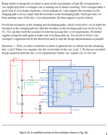
Transcribed Image Text:Being unable to design the oscillator to meet all the requirements of part (B) of experiment 1,
you sought help from a colleague who is heading out to attend a meeting. Your colleague takes a
quick look at your design (equations, circuit diagram etc.) and suggests the resistance in the
charging path is always larger than the resistance in the discharging path, which prevents you
from meeting some of the duty cycle requirements. He then suggests a quick solution
Switch the resistances in the charging and discharging paths, which would allow you to make the
resistance in the charging path less than the resistance in the discharge path (see circuit in Fig.
10). You can then build the oscillator to meet the missing duty cycle requirements. He further
suggests doing the math again to make sure everything adds up. You decide to follow your
colleague's suggestion but do the theoretical analysis and the design implementation in parallel.
Questions: 1. Were you able to build the oscillator to generate the waveforms for the remaining
duty cycles? Either way explains why the circuit behaved the way it did. 2. Do the new/modified
design equations meet the duty cycle requirements? Either way, explain why or why not.
Voc
charge Icc
8
Voc
w
R₁
www
Reset
4
Discharge
discharge
Threshold
5
6
Trigger
2
Control
5
RST
R
Q
S
e
1
Ground
Out
3
Figure 10: A modified version of the oscillator shown in Fig. (9).
Expert Solution
This question has been solved!
Explore an expertly crafted, step-by-step solution for a thorough understanding of key concepts.
Step by stepSolved in 2 steps

Knowledge Booster
Recommended textbooks for you
 Introductory Circuit Analysis (13th Edition)Electrical EngineeringISBN:9780133923605Author:Robert L. BoylestadPublisher:PEARSON
 Delmar's Standard Textbook Of ElectricityElectrical EngineeringISBN:9781337900348Author:Stephen L. HermanPublisher:Cengage Learning
 Programmable Logic ControllersElectrical EngineeringISBN:9780073373843Author:Frank D. PetruzellaPublisher:McGraw-Hill Education
 Fundamentals of Electric CircuitsElectrical EngineeringISBN:9780078028229Author:Charles K Alexander, Matthew SadikuPublisher:McGraw-Hill Education
 Electric Circuits. (11th Edition)Electrical EngineeringISBN:9780134746968Author:James W. Nilsson, Susan RiedelPublisher:PEARSON
 Engineering ElectromagneticsElectrical EngineeringISBN:9780078028151Author:Hayt, William H. (william Hart), Jr, BUCK, John A.Publisher:Mcgraw-hill Education,

Introductory Circuit Analysis (13th Edition)
Electrical Engineering
ISBN:9780133923605
Author:Robert L. Boylestad
Publisher:PEARSON

Delmar's Standard Textbook Of Electricity
Electrical Engineering
ISBN:9781337900348
Author:Stephen L. Herman
Publisher:Cengage Learning

Programmable Logic Controllers
Electrical Engineering
ISBN:9780073373843
Author:Frank D. Petruzella
Publisher:McGraw-Hill Education

Fundamentals of Electric Circuits
Electrical Engineering
ISBN:9780078028229
Author:Charles K Alexander, Matthew Sadiku
Publisher:McGraw-Hill Education

Electric Circuits. (11th Edition)
Electrical Engineering
ISBN:9780134746968
Author:James W. Nilsson, Susan Riedel
Publisher:PEARSON

Engineering Electromagnetics
Electrical Engineering
ISBN:9780078028151
Author:Hayt, William H. (william Hart), Jr, BUCK, John A.
Publisher:Mcgraw-hill Education,