
Introductory Circuit Analysis (13th Edition)
13th Edition
ISBN: 9780133923605
Author: Robert L. Boylestad
Publisher: PEARSON
expand_more
expand_more
format_list_bulleted
Related questions
Concept explainers
Question
show solution thank you.
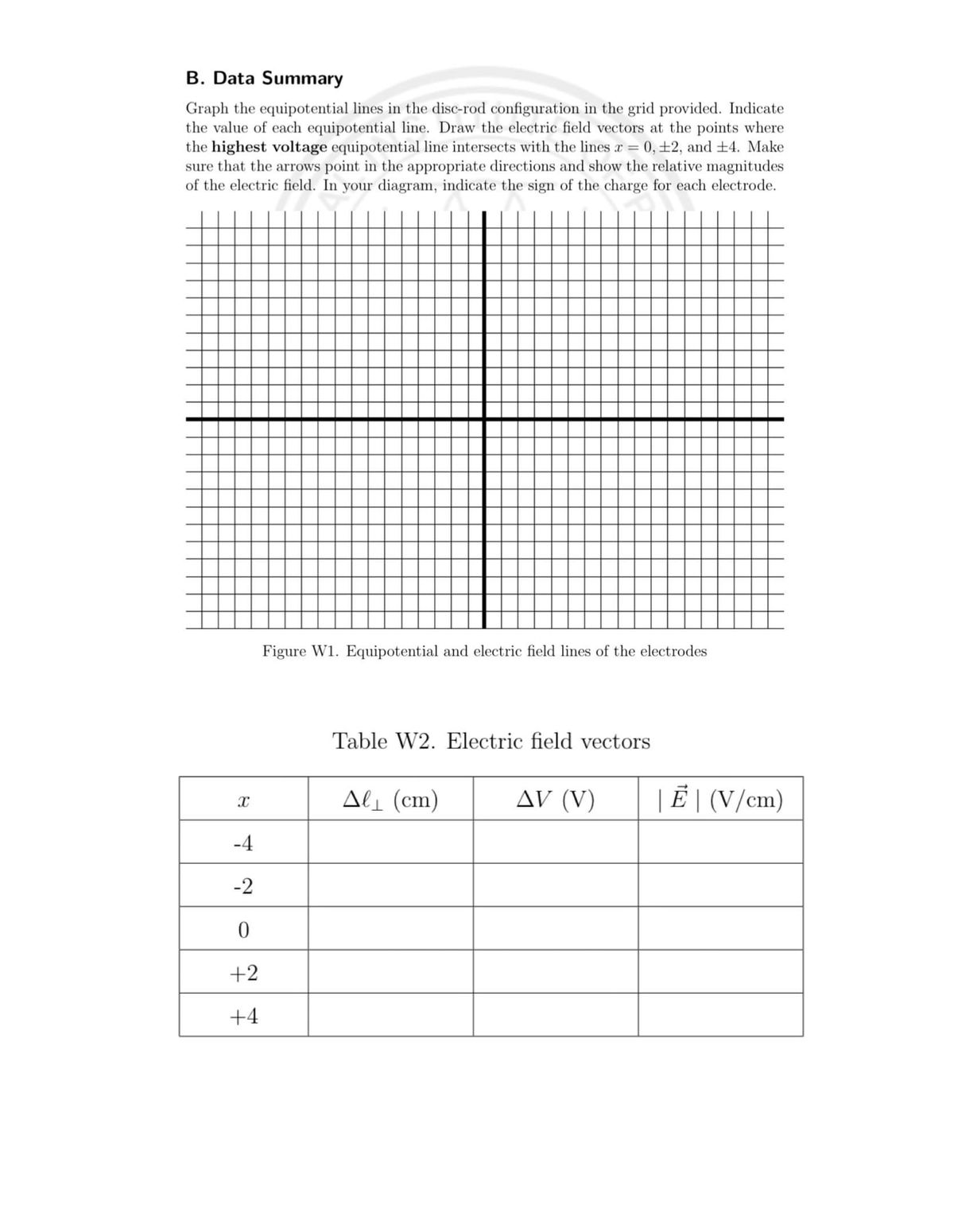

Transcribed Image Text:B. Data Summary
Graph the equipotential lines in the disc-rod configuration in the grid provided. Indicate
the value of each equipotential line. Draw the electric field vectors at the points where
the highest voltage equipotential line intersects with the lines r = 0, ±2, and +4. Make
sure that the arrows point in the appropriate directions and show the relative magnitudes
of the electric field. In your diagram, indicate the sign of the charge for each electrode.
Figure W1. Equipotential and electric field lines of the electrodes
Table W2. Electric field vectors
Ali (cm)
AV (V)
| Ë | (V/cm)
-4
-2
0.
+2
+4

Transcribed Image Text:Raw Data (x-y coordinates of certain voltage values)
Voltage (V) = 8.0V
Voltage (V) = 7.0V
Voltage (V) = 6.0V
х (ст)
y (cm)
х (ст)
y (cm)
х (сm)
у (сm)
6.00
4.75
6.00
2.00
6.00
-0.25
4.00
3.75
4.00
1.75
4,00
-0.50
2.00
3.00
2.00
1.50
2.00
-0.25
0.00
2.75
0.00
1.00
0.00
-0.25
-2.00
3.00
-2.00
1.25
-2.00
-0.25
-4.00
3.75
-4.00
1.50
-4.00
-0.25
-6.00
4.50
-6,00
2.00
-6.00
-0,25
Voltage (V) = 5.0V
Voltage (V) = 4.0V
Voltage (V) = 3.0V
х (ст)
y (cm)
x (cm)
у (ст)
х (ст)
у (ст)
6.00
-2.75
6.00
-5.00
6.00
-7.00
4.00
-2.25
4.00
-4.00
4.00
-5.25
2.00
-2.00
2.00
-3.75
2.00
-5.00
0.00
-2.00
0,00
-3.25
0.00
-4.75
-2.00
-2.00
-2.00
-3.25
-2.00
-4.75
-4.00
-2.00
-4.00
-3.50
-4.00
-5.00
-6.00
-2.50
-6.00
-4.75
-6.00
-7.50
Rod Voltage: 0Vv
х (сm)
Disk Voltage: 12.0V
x (cm)
у (ст)
у (cт)
0.00
8.00
0.00
-8.00
Equation 7
|vvlp = lim
%3D
ALL>0 Al
Expert Solution
This question has been solved!
Explore an expertly crafted, step-by-step solution for a thorough understanding of key concepts.

Step by stepSolved in 4 steps with 2 images

Knowledge Booster


Learn more about
Need a deep-dive on the concept behind this application? Look no further. Learn more about this topic, electrical-engineering and related others by exploring similar questions and additional content below.Similar questions
- Q/ In DC machines, the external characteristics are plotted between Ans/ 1- Eg vs load current 2- Vt vs Ia 3- Eg vs Ia 4- Vt vs load currentarrow_forwardNeeds Complete typed solution with 100 % accuracy.arrow_forwardDiscuss the role of power system protection devices and their importance in preventing electrical failures.arrow_forward
- Write few points about combinational circuits?arrow_forward3. A dad ful comirester, Conneet ed to 230 v, fo Mz. Sousie bf. feedng a locel R: 10 n n senies wish a levnge Induadomre thad makes the load lenent rippie free · for a firing anyle of ur°, ewewlade the input and oatpud performante panametess of thik comveater.arrow_forwardDefine "ideal" and "currently available" standards and provide a brief explanation as to how they are used in setting standards.arrow_forward
- 1-Identify and Explain with neat sketch of the a).Shackle Insulator 2-What do you understand by Safety factor, puncture and Flashover of Insulatorarrow_forwardShow that Circuit (II) is simplified version of Circuit (I). Hint: Use reference table.arrow_forwarda) Find the value of resistor using colour code (Brown-Orange-Gold-Silver). b) Suppose the measured value of resistor using DMM is 1.9 2. Is the within tolerance limit of resistor? c) Find the absolute and relative error of colour coded value of resistance and measured resistance using DMM.arrow_forward
arrow_back_ios
SEE MORE QUESTIONS
arrow_forward_ios
Recommended textbooks for you
- Introductory Circuit Analysis (13th Edition)Electrical EngineeringISBN:9780133923605Author:Robert L. BoylestadPublisher:PEARSON
 Delmar's Standard Textbook Of ElectricityElectrical EngineeringISBN:9781337900348Author:Stephen L. HermanPublisher:Cengage Learning
 Programmable Logic ControllersElectrical EngineeringISBN:9780073373843Author:Frank D. PetruzellaPublisher:McGraw-Hill Education
  Fundamentals of Electric CircuitsElectrical EngineeringISBN:9780078028229Author:Charles K Alexander, Matthew SadikuPublisher:McGraw-Hill Education
 Electric Circuits. (11th Edition)Electrical EngineeringISBN:9780134746968Author:James W. Nilsson, Susan RiedelPublisher:PEARSON
 Engineering ElectromagneticsElectrical EngineeringISBN:9780078028151Author:Hayt, William H. (william Hart), Jr, BUCK, John A.Publisher:Mcgraw-hill Education,
Introductory Circuit Analysis (13th Edition)
Electrical Engineering
ISBN:9780133923605
Author:Robert L. Boylestad
Publisher:PEARSON
Delmar's Standard Textbook Of Electricity
Electrical Engineering
ISBN:9781337900348
Author:Stephen L. Herman
Publisher:Cengage Learning
Programmable Logic Controllers
Electrical Engineering
ISBN:9780073373843
Author:Frank D. Petruzella
Publisher:McGraw-Hill Education
Fundamentals of Electric Circuits
Electrical Engineering
ISBN:9780078028229
Author:Charles K Alexander, Matthew Sadiku
Publisher:McGraw-Hill Education
Electric Circuits. (11th Edition)
Electrical Engineering
ISBN:9780134746968
Author:James W. Nilsson, Susan Riedel
Publisher:PEARSON
Engineering Electromagnetics
Electrical Engineering
ISBN:9780078028151
Author:Hayt, William H. (william Hart), Jr, BUCK, John A.
Publisher:Mcgraw-hill Education,