
Introductory Circuit Analysis (13th Edition)
13th Edition
ISBN: 9780133923605
Author: Robert L. Boylestad
Publisher: PEARSON
expand_more
expand_more
format_list_bulleted
Related questions
Concept explainers
Question
need help on this option 2,thanks
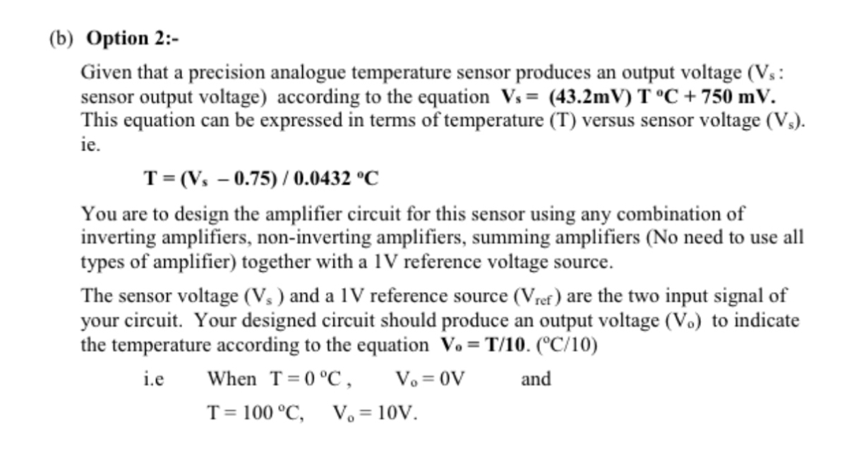

Transcribed Image Text:(b) Option 2:-
Given that a precision analogue temperature sensor produces an output voltage (Vs:
sensor output voltage) according to the equation Vs= (43.2mV) T °C + 750 mV.
This equation can be expressed in terms of temperature (T) versus sensor voltage (V₂).
ie.
T=(Vs -0.75)/ 0.0432 °C
You are to design the amplifier circuit for this sensor using any combination of
inverting amplifiers, non-inverting amplifiers, summing amplifiers (No need to use all
types of amplifier) together with a 1V reference voltage source.
The sensor voltage (V₁) and a 1V reference source (Vref) are the two input signal of
your circuit. Your designed circuit should produce an output voltage (V.) to indicate
the temperature according to the equation V.= T/10. (°C/10)
i.e
and
When T=0 °C, Vo = OV
T = 100 °C, V₂ = 10V.
Expert Solution
This question has been solved!
Explore an expertly crafted, step-by-step solution for a thorough understanding of key concepts.

Step by stepSolved in 5 steps with 5 images

Knowledge Booster


Learn more about
Need a deep-dive on the concept behind this application? Look no further. Learn more about this topic, electrical-engineering and related others by exploring similar questions and additional content below.Similar questions
- 5. Materials that increase their resistance with an increase in temperature have a _____ coefficient of temperature. Select one: A. POSITIVE B. NEGATIVEarrow_forwardExercise 2 (from chapter 6) For the diagram below, set up the following items; Kirchhoff loop for the bottom loop of the diagram. Kirchhoff loop for the top loop of the diagram. Kirchhoff loop for junctions A and B.arrow_forwardPlz answer this ASAP Two resistors 15 and 20 respectively are connected in parallel and then connected in series with a resistor 10 2. The resistor circuit is connected to the terminal voltage X Volts. X=110 volts A.)Make an electrical circuit B.)Calculate the current flowing through each resistor.arrow_forward
Recommended textbooks for you
- Introductory Circuit Analysis (13th Edition)Electrical EngineeringISBN:9780133923605Author:Robert L. BoylestadPublisher:PEARSON
 Delmar's Standard Textbook Of ElectricityElectrical EngineeringISBN:9781337900348Author:Stephen L. HermanPublisher:Cengage Learning
 Programmable Logic ControllersElectrical EngineeringISBN:9780073373843Author:Frank D. PetruzellaPublisher:McGraw-Hill Education
  Fundamentals of Electric CircuitsElectrical EngineeringISBN:9780078028229Author:Charles K Alexander, Matthew SadikuPublisher:McGraw-Hill Education
 Electric Circuits. (11th Edition)Electrical EngineeringISBN:9780134746968Author:James W. Nilsson, Susan RiedelPublisher:PEARSON
 Engineering ElectromagneticsElectrical EngineeringISBN:9780078028151Author:Hayt, William H. (william Hart), Jr, BUCK, John A.Publisher:Mcgraw-hill Education,
Introductory Circuit Analysis (13th Edition)
Electrical Engineering
ISBN:9780133923605
Author:Robert L. Boylestad
Publisher:PEARSON
Delmar's Standard Textbook Of Electricity
Electrical Engineering
ISBN:9781337900348
Author:Stephen L. Herman
Publisher:Cengage Learning
Programmable Logic Controllers
Electrical Engineering
ISBN:9780073373843
Author:Frank D. Petruzella
Publisher:McGraw-Hill Education
Fundamentals of Electric Circuits
Electrical Engineering
ISBN:9780078028229
Author:Charles K Alexander, Matthew Sadiku
Publisher:McGraw-Hill Education
Electric Circuits. (11th Edition)
Electrical Engineering
ISBN:9780134746968
Author:James W. Nilsson, Susan Riedel
Publisher:PEARSON
Engineering Electromagnetics
Electrical Engineering
ISBN:9780078028151
Author:Hayt, William H. (william Hart), Jr, BUCK, John A.
Publisher:Mcgraw-hill Education,