Introductory Circuit Analysis (13th Edition)
13th Edition
ISBN: 9780133923605
Author: Robert L. Boylestad
Publisher: PEARSON
expand_more
expand_more
format_list_bulleted
Question

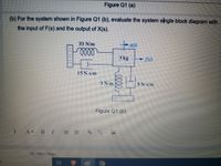
Transcribed Image Text:Figure Q1 (a)
(b) For the system shown in Figure Q1 (b), evaluate the system single block diagram with
the input of F(s) and the output of X(s).
33 N/m
3 kg
15 N-s/m
3 N/m
5N-sm
Figure Q1 (b)
A BI
19 1366 x 768px
II
!!
Expert Solution
This question has been solved!
Explore an expertly crafted, step-by-step solution for a thorough understanding of key concepts.
Step by stepSolved in 2 steps with 2 images

Knowledge Booster
Learn more about
Need a deep-dive on the concept behind this application? Look no further. Learn more about this topic, electrical-engineering and related others by exploring similar questions and additional content below.Similar questions
- 14 digital electronics The clock signal and inputs applied in the circuit given in the figure are shown. Accordingly, in which option is the sign obtained at the output given correctly? a)there is no output according to this data b)W1 c)W4 d)none e)W2 f)W3arrow_forwardanswer fastarrow_forwardMake a Kmap for the state table and draw a circuit diagram, please.arrow_forward
- I need the answer as soon as possiblearrow_forwardShow all the steps while analyzing the following sequential circuit. Include input, Output and Characteristic equation, State Equation cate Table and State Diagram. S1 Q1 R, *1. R JO x'- KO Karrow_forwardHow do i use source trasnformation to find the current? Using KCL I got -.25mA and thats not right.arrow_forward
- Do not copy from other websites Correct and detailed answer will be Upvoted else downvoted. Thank you!arrow_forwardConsider the diode circuit shown below. If in the given circuit, Vs is replaced by a 12V battery and diodes D1 & D2 are considered ideal, what is the potential Vout equal to?arrow_forwardQ. Determine the output of the DAC in figure (a) if the sequence of 4-bit numbers in part (b) is applied to the inputs. The data inputs have a low value of 0 V and a high value of +5 V. 200 ΚΩ 10 ΚΩ ww Do Do o 100 ΚΩ D₁0 D₂0-M 25 ΚΩ D₂0M (a) 50 ΚΩ Output D₁ D₂ D3 (b)arrow_forward
arrow_back_ios
SEE MORE QUESTIONS
arrow_forward_ios
Recommended textbooks for you
 Introductory Circuit Analysis (13th Edition)Electrical EngineeringISBN:9780133923605Author:Robert L. BoylestadPublisher:PEARSON
 Delmar's Standard Textbook Of ElectricityElectrical EngineeringISBN:9781337900348Author:Stephen L. HermanPublisher:Cengage Learning
 Programmable Logic ControllersElectrical EngineeringISBN:9780073373843Author:Frank D. PetruzellaPublisher:McGraw-Hill Education
 Fundamentals of Electric CircuitsElectrical EngineeringISBN:9780078028229Author:Charles K Alexander, Matthew SadikuPublisher:McGraw-Hill Education
 Electric Circuits. (11th Edition)Electrical EngineeringISBN:9780134746968Author:James W. Nilsson, Susan RiedelPublisher:PEARSON
 Engineering ElectromagneticsElectrical EngineeringISBN:9780078028151Author:Hayt, William H. (william Hart), Jr, BUCK, John A.Publisher:Mcgraw-hill Education,

Introductory Circuit Analysis (13th Edition)
Electrical Engineering
ISBN:9780133923605
Author:Robert L. Boylestad
Publisher:PEARSON

Delmar's Standard Textbook Of Electricity
Electrical Engineering
ISBN:9781337900348
Author:Stephen L. Herman
Publisher:Cengage Learning

Programmable Logic Controllers
Electrical Engineering
ISBN:9780073373843
Author:Frank D. Petruzella
Publisher:McGraw-Hill Education

Fundamentals of Electric Circuits
Electrical Engineering
ISBN:9780078028229
Author:Charles K Alexander, Matthew Sadiku
Publisher:McGraw-Hill Education

Electric Circuits. (11th Edition)
Electrical Engineering
ISBN:9780134746968
Author:James W. Nilsson, Susan Riedel
Publisher:PEARSON

Engineering Electromagnetics
Electrical Engineering
ISBN:9780078028151
Author:Hayt, William H. (william Hart), Jr, BUCK, John A.
Publisher:Mcgraw-hill Education,