Introductory Circuit Analysis (13th Edition)
13th Edition
ISBN: 9780133923605
Author: Robert L. Boylestad
Publisher: PEARSON
expand_more
expand_more
format_list_bulleted
Question

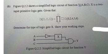
Transcribed Image Text:(b) Figure Q.2.2 shows a simplified logic circuit of function X(A,B,C). X is a two-
input primitive logic gate. Given that:
0(0,0,0) =0(0,2,4,5,6)
Determine the type of logic gate X. Show your working steps.
A
B
ar
C
Figure Q.2.2: Simplified logic circuit for function Y
X
Expert Solution
This question has been solved!
Explore an expertly crafted, step-by-step solution for a thorough understanding of key concepts.
Step by stepSolved in 2 steps with 2 images

Knowledge Booster
Learn more about
Need a deep-dive on the concept behind this application? Look no further. Learn more about this topic, electrical-engineering and related others by exploring similar questions and additional content below.Similar questions
- 5/ Select a suitable example for combinational logic circuit. A) None of the given choices B) Decoders C) Latches D ) PLAarrow_forwardConsider the circuit below. The switches are controlled by logic variables such that, if A is high, switch A is closed, and if A is low, switch A is open. Conversely, if B is high, the switch labeled is open, and if B is low, the switch labeled is closed. The output variable is high if the output voltage is 5V, and the output variable is low if the output voltage is zero. a. Write a logic expression for the output variable. b. Construct the truth table for the circuit. A Logic 1 5V(+ B C Logic 0 Rarrow_forward(a) Find VH and VL for the Schottky DTL gateshown. (b) What are the input currents in thetwo logic states? (c) What is the fanout of the gate?arrow_forward
- Please do part b using the Assumptionarrow_forwardDesign the following combinational logic circuit with a four-bit input and a three-bit output. The input represents two unsigned 2-bit numbers: A1 A0 and B1 B0. The output C2 C1.C0 is the result of the integer binary division A1 A0/B1 B0 rounded down to three bits. The 3-bit output has a 2-bit unsigned whole part C2 C1 and a fraction part CO. The weight of the fraction bit CO is 21. Note the quotient should be rounded down, i.e. the division 01/11 should give the outputs 00.0 (1/3 rounded down to 0) not 00.1 (1/3 rounded up to 0.5). A result of infinity should be represented as 11.1. A minimal logic implementation is not required. (Hint: start by producing a truth table of your design).arrow_forwardReduce the Boolean function specified in the truth table below to its minimum SOP form using K-map, where A, B, C are the inputs while X are the outputs. Based on the reduced Boolean function, design the logic circuit using any logic gates. A 0 0 0 0 1 1 1 1 B 0 0 1 1 0 1 с 0 1 0 1 0 1 0 1 X 1 1 0 1 1 1 0 1arrow_forward
- What will be the boolean function (y) for the given CMOS logic circuit as shown in the figure? AMP, MP₂-B MP3 A—IL MN, BCMN₂ D- V₂ HCMN₂ DD MP -D MP-E y MN3C GND MNEarrow_forwardA. One way to think of the basic logic gate types (all but the EXOR and EXNOR) is to consider what single input state guarantees a certain output state. For example, we could describe the function of an OR gate as such: “Any high input guarantees a high output.” Identify what type of gate is represented by each of the following phrases: a) Any high input guarantees a low output. b) Any low input guarantees a high output. c) Any low input guarantees a low output.arrow_forwardThe question is in the picture below.arrow_forward
- What are the values of the inputs a, b, c, d, e, f and g for a Seven-Segment LED that displays the number 2? Assume active high logic. a) 1101101 b) 1010101 c) 1101110 d) None of the above e) All of the abovearrow_forwarda) Design a combinational circuit that would take a 3-bit binary number and generate an output if the input value in decimal is either divisible by 2 or 3. iii) Explain and show how you would implement this circuit using a 4-to-1 Multiplexer and other appropriate logic gates. Use a block diagram for the multiplexer.arrow_forwardpole. 50-Hz. 3-ϕ induction motor has a full-load speed of 950 rpm. At half load its speed would be ..... rpm a) 475 b) 500 c) 975 d)1000arrow_forward
arrow_back_ios
SEE MORE QUESTIONS
arrow_forward_ios
Recommended textbooks for you
 Introductory Circuit Analysis (13th Edition)Electrical EngineeringISBN:9780133923605Author:Robert L. BoylestadPublisher:PEARSON
 Delmar's Standard Textbook Of ElectricityElectrical EngineeringISBN:9781337900348Author:Stephen L. HermanPublisher:Cengage Learning
 Programmable Logic ControllersElectrical EngineeringISBN:9780073373843Author:Frank D. PetruzellaPublisher:McGraw-Hill Education
 Fundamentals of Electric CircuitsElectrical EngineeringISBN:9780078028229Author:Charles K Alexander, Matthew SadikuPublisher:McGraw-Hill Education
 Electric Circuits. (11th Edition)Electrical EngineeringISBN:9780134746968Author:James W. Nilsson, Susan RiedelPublisher:PEARSON
 Engineering ElectromagneticsElectrical EngineeringISBN:9780078028151Author:Hayt, William H. (william Hart), Jr, BUCK, John A.Publisher:Mcgraw-hill Education,

Introductory Circuit Analysis (13th Edition)
Electrical Engineering
ISBN:9780133923605
Author:Robert L. Boylestad
Publisher:PEARSON

Delmar's Standard Textbook Of Electricity
Electrical Engineering
ISBN:9781337900348
Author:Stephen L. Herman
Publisher:Cengage Learning

Programmable Logic Controllers
Electrical Engineering
ISBN:9780073373843
Author:Frank D. Petruzella
Publisher:McGraw-Hill Education

Fundamentals of Electric Circuits
Electrical Engineering
ISBN:9780078028229
Author:Charles K Alexander, Matthew Sadiku
Publisher:McGraw-Hill Education

Electric Circuits. (11th Edition)
Electrical Engineering
ISBN:9780134746968
Author:James W. Nilsson, Susan Riedel
Publisher:PEARSON

Engineering Electromagnetics
Electrical Engineering
ISBN:9780078028151
Author:Hayt, William H. (william Hart), Jr, BUCK, John A.
Publisher:Mcgraw-hill Education,