Structural Analysis
6th Edition
ISBN: 9781337630931
Author: KASSIMALI, Aslam.
Publisher: Cengage,
expand_more
expand_more
format_list_bulleted
Question

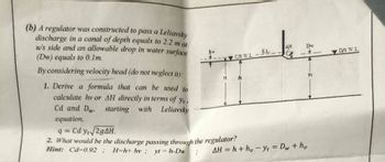
Transcribed Image Text:(b) A regulator was constructed to pass a Leliavsky
discharge in a canal of depth equals to 2.2 m at
u/s side and an allowable drop in water surface
(Dw) equals to 0.1m.
By considering velocity head (do not neglect it):
1. Derive a formula that can be used to
calculate hy or AH directly in terms of yt
Cd and Dw,
equation,
starting with Leliavsky
q= Cd y√√2gAH.
2. What would be the discharge passing through the regulator?
Hint: Cd-0.92; H-h+ hv; yt-h-Dw
US WL
ΔΗ
Dw
E.L.
-
AH=h+h, yt = Dw + hv
yt
D/S W.L.
Expert Solution
This question has been solved!
Explore an expertly crafted, step-by-step solution for a thorough understanding of key concepts.
Step by stepSolved in 2 steps

Knowledge Booster
Similar questions
- z=174 m A B z=152 m z=91 m T = and Op ≈pg əx (Pump) C F A pump is used to deliver water from a reservoir to a large tank for a flowrate of 1310 L/s at 20 °C. The connecting pipe connects the reservoir at B with a square-edged entrance. From B to C, the pipe is 760 m long and has three gate valves, four 45⁰ elbows, and two 90° elbows. Gage pressure at C is 197 kPa. From F to G, the pipe is 760 m long and contains two gate valves (Kg.-0.136), four 90° elbows (K90-0.51) and connects the tank with an exit (Kext=1). All pipe is 508 mm in diameter (D) and made by cast iron ( = 0.26 mm). 1) Calculate the average velocity of water in the pipe. 2) Calculate the gage pressure at F. z=104 m 3) If the pump's efficiency is 80%, calculate the power input to the pump. 4) If the shear stress can be calculated using the equation D Op hL major 4 0x L Calculate the average wall shear stress in section F-G. G Harrow_forwardTrapezoidal cross section given in the figure on the side It is requested to pass a flow rate of 5 m/s through the channel. Accepting that n=0.0167 and Jo=0.0005 in this section; size the cross section to be optimal from the hydraulic direction.arrow_forwardPlease give correct answer Subject is fluid mechanicsarrow_forward
- Water flow passes under the sluice gate. Suppose that y₁ = 6 m and y2 = 1.9 m. (Figure 1) Figure Y₁ 4 m Y₂ 1 of 1 Part B Determine the critical depth of the flow downstream from the gate. Express your answer to three significant figures and include the appropriate units. Ye= 3.095 Submit m Previous Answers Request Answer X Incorrect; Try Again; 4 attempts remainingarrow_forwardThe total discharge (flowrate) from A to B in the figure below is 300 liters/s. Pipe lennthe are: L1= 150 m, and L2 = 450 m. Diameters, are: D1 = 500 mm, and D2 = 250 mm. L1:D1 Q1 Q Q2 L2; D2 Determine [Using Darcy's equation] the headloss [m] and the flowrates (/s] across A-B in pipes 1 and 2 if riyated steel iron pipes are used in the system and flow is FULLY TURBULENT. Flowrate pipe #1 [I/s] =- Flowrate pipe #2 [l/s] =- Headloss pipe #1 [m] =. %3D Headloss pipe #2 [m]arrow_forward
arrow_back_ios
arrow_forward_ios
Recommended textbooks for you

 Structural Analysis (10th Edition)Civil EngineeringISBN:9780134610672Author:Russell C. HibbelerPublisher:PEARSON
 Principles of Foundation Engineering (MindTap Cou...Civil EngineeringISBN:9781337705028Author:Braja M. Das, Nagaratnam SivakuganPublisher:Cengage Learning
 Fundamentals of Structural AnalysisCivil EngineeringISBN:9780073398006Author:Kenneth M. Leet Emeritus, Chia-Ming Uang, Joel LanningPublisher:McGraw-Hill Education
 Traffic and Highway EngineeringCivil EngineeringISBN:9781305156241Author:Garber, Nicholas J.Publisher:Cengage Learning


Structural Analysis (10th Edition)
Civil Engineering
ISBN:9780134610672
Author:Russell C. Hibbeler
Publisher:PEARSON

Principles of Foundation Engineering (MindTap Cou...
Civil Engineering
ISBN:9781337705028
Author:Braja M. Das, Nagaratnam Sivakugan
Publisher:Cengage Learning

Fundamentals of Structural Analysis
Civil Engineering
ISBN:9780073398006
Author:Kenneth M. Leet Emeritus, Chia-Ming Uang, Joel Lanning
Publisher:McGraw-Hill Education


Traffic and Highway Engineering
Civil Engineering
ISBN:9781305156241
Author:Garber, Nicholas J.
Publisher:Cengage Learning