Introductory Circuit Analysis (13th Edition)
13th Edition
ISBN: 9780133923605
Author: Robert L. Boylestad
Publisher: PEARSON
expand_more
expand_more
format_list_bulleted
Concept explainers
Question
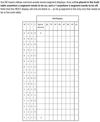
This is the next part of the worksheet but I totally get if only the truth table may be solved. Thank you!
For each of the 8 outputs in the truth-table, construct a K-Map to determine the
simplest Boolean expression. Be sure to look for XOR and XNOR simplifications to
reduce you final gate count. For example: XY’Z + XYZ’ = X(Y xor Z). Since segments a-f
of HEX1 will always be off, k-maps are necessary.

Transcribed Image Text:the DE board utilizes common-anode seven-segment displays, thus; a 0 is placed in the truth
table anywhere a segment needs to be on, and a 1 anywhere a segment needs to be off.
Note that the HEX1 display will only be blank or -, so its g segment is the only one that needs to
be in the truth table.
W X Y Z Signed go
decimal
。。。。。
0
0
0010
0
0
0
0
1
1
1
1
1
1
O
1
1
1
1
O
1
O
1
1
0
1 0
1
1
1
1
O
1
0
1
1 0 1
1 1 10
0
1
-1
HEX Displays
fo eo
do co
g
b0
а 0 g1
Expert Solution
This question has been solved!
Explore an expertly crafted, step-by-step solution for a thorough understanding of key concepts.
This is a popular solution
Trending nowThis is a popular solution!
Step by stepSolved in 2 steps with 2 images

Follow-up Questions
Read through expert solutions to related follow-up questions below.
Follow-up Question
may you display this in a circuit schematic? thank you
Solution
by Bartleby Expert
Follow-up Questions
Read through expert solutions to related follow-up questions below.
Follow-up Question
may you display this in a circuit schematic? thank you
Solution
by Bartleby Expert
Knowledge Booster
Learn more about
Need a deep-dive on the concept behind this application? Look no further. Learn more about this topic, electrical-engineering and related others by exploring similar questions and additional content below.Similar questions
- use the picture provided, where we filled out the truth table for the 2-bit adder. We also wrote out a logical expression for the s0 bit, following a sum of products approach. For the s1 bit of the new circuit, follow the same procedure and write out the logical expression.arrow_forwardExplain whats going on SIMPLY!arrow_forwardUsing the laws of boolean algebra simplify these expressions and list the law(s) used to justify each step. And show a truth table for the original expression and verify that your final expression satisfies the same truth table. a. A' + A'B'CD' + A'B'C'D' + AB'C' + AB'CD' + ABD + BC'D b. A'B' + A'BC' + (A + C')'arrow_forward
arrow_back_ios
arrow_forward_ios
Recommended textbooks for you
 Introductory Circuit Analysis (13th Edition)Electrical EngineeringISBN:9780133923605Author:Robert L. BoylestadPublisher:PEARSON
 Delmar's Standard Textbook Of ElectricityElectrical EngineeringISBN:9781337900348Author:Stephen L. HermanPublisher:Cengage Learning
 Programmable Logic ControllersElectrical EngineeringISBN:9780073373843Author:Frank D. PetruzellaPublisher:McGraw-Hill Education
 Fundamentals of Electric CircuitsElectrical EngineeringISBN:9780078028229Author:Charles K Alexander, Matthew SadikuPublisher:McGraw-Hill Education
 Electric Circuits. (11th Edition)Electrical EngineeringISBN:9780134746968Author:James W. Nilsson, Susan RiedelPublisher:PEARSON
 Engineering ElectromagneticsElectrical EngineeringISBN:9780078028151Author:Hayt, William H. (william Hart), Jr, BUCK, John A.Publisher:Mcgraw-hill Education,

Introductory Circuit Analysis (13th Edition)
Electrical Engineering
ISBN:9780133923605
Author:Robert L. Boylestad
Publisher:PEARSON

Delmar's Standard Textbook Of Electricity
Electrical Engineering
ISBN:9781337900348
Author:Stephen L. Herman
Publisher:Cengage Learning

Programmable Logic Controllers
Electrical Engineering
ISBN:9780073373843
Author:Frank D. Petruzella
Publisher:McGraw-Hill Education

Fundamentals of Electric Circuits
Electrical Engineering
ISBN:9780078028229
Author:Charles K Alexander, Matthew Sadiku
Publisher:McGraw-Hill Education

Electric Circuits. (11th Edition)
Electrical Engineering
ISBN:9780134746968
Author:James W. Nilsson, Susan Riedel
Publisher:PEARSON

Engineering Electromagnetics
Electrical Engineering
ISBN:9780078028151
Author:Hayt, William H. (william Hart), Jr, BUCK, John A.
Publisher:Mcgraw-hill Education,