
Related questions
Concept explainers
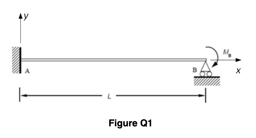
A propped cantilever beam is loaded by a bending moment of the magnitude M_B at the point B as shown in Figure Q1. The cross-section of the beam is a rectangle of the width w and the hight ℎ that are constant along the length of the beam L. The beam material’s Young’s modulus is Q.
Assuming the positive deflections and positive vertical reaction forces are upward, calculate
-
- the value of the reaction forces at points A and B
- the absolute value of the reaction bending moment at point A
A) Let R represent the reaction force at Support B. By releasing the beam at Support B and imposing a force R at Point B, the deflection of the beam consists of two parts,i.e.
Part I- the deflection caused by M_B ;
Part II- the deflection caused by R
Please treat R, w, h , L , E as variables in this step , the mathematical equation for the deflection at Point B caused by R ( Part II) can be written as:
b)
Using the provided data:
- cross-section width w = 14 mm,
- cross-section hight h = 82 mm,
- length of the beam L =2 m ,
- beam material’s Young’s modulus Q =233 GPa,
- applied bending moment M_B = 9 kN.m
The value of the deflection at Point B caused by M_B ( Part I) can be calculated as: __mm
c)
Based on the given values of dimensions and material parameters,
- the value of R can be calculated as __ kN;
- the value of the vertical reaction force at Support A can be calculated as __ kN;
- the value of the horizontal reaction force at Support A can be calculated as __ kN
- the absolute value of the reaction moment at Support A can be calculated as __ kN.m


Step by stepSolved in 4 steps with 4 images


- Solve using DIM. Previous answer here was wrong so please correct it.arrow_forward(a) derive equations for the shear force V and the bending momentM for any location in the beam. (Place the origin at point A.)(b) use the derived functions to plot the shear-force and bendingmomentdiagrams for the beam.(c) specify the values for key points on the diagrams.arrow_forwardThe channel shape cross-section and the rectangular cross-section shown in the Figure Q4 are made of materials with elastic-perfectly plastic behaviour. The yield stress of the material used for the channel shape cross-section is oy = 473 MPa, whereas that used for the rectangular cross- section is 0.850y. Compute the thickness of the web, t, of the channel shape section if the two cross sections have identical plastic bending moment about the z-axis. In Figure 4, h= 77 mm, b=46 mm, a=11 mm, H=77 mm, d= 46 mm N b h a + N a | d Harrow_forward
- Elements Of ElectromagneticsMechanical EngineeringISBN:9780190698614Author:Sadiku, Matthew N. O.Publisher:Oxford University Press
 Mechanics of Materials (10th Edition)Mechanical EngineeringISBN:9780134319650Author:Russell C. HibbelerPublisher:PEARSON
 Thermodynamics: An Engineering ApproachMechanical EngineeringISBN:9781259822674Author:Yunus A. Cengel Dr., Michael A. BolesPublisher:McGraw-Hill Education
  Control Systems EngineeringMechanical EngineeringISBN:9781118170519Author:Norman S. NisePublisher:WILEY
 Mechanics of Materials (MindTap Course List)Mechanical EngineeringISBN:9781337093347Author:Barry J. Goodno, James M. GerePublisher:Cengage Learning
 Engineering Mechanics: StaticsMechanical EngineeringISBN:9781118807330Author:James L. Meriam, L. G. Kraige, J. N. BoltonPublisher:WILEY