Related questions
Question
thumb_up100%
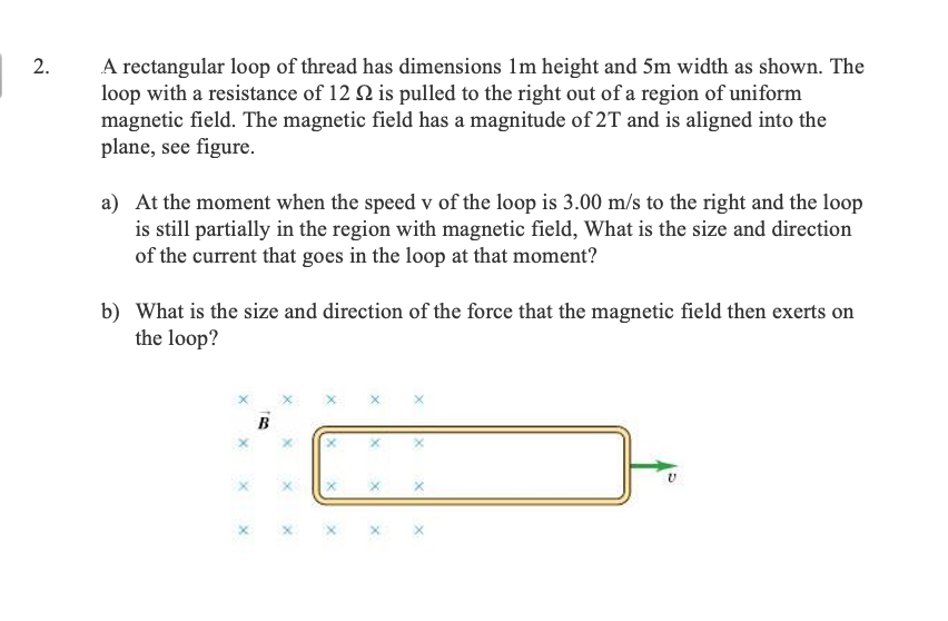
A rectangular loop of thread has dimensions 1m height and 5m width as shown. The loop with a resistance of 12 Ω is pulled to the right out of a region of uniform magnetic field. The magnetic field has a magnitude of 2T and is aligned into the plane, see figure.
a) At the moment when the speed v of the loop is 3.00 m/s to the right and the loop is still partially in the region with magnetic field, What is the size and direction of the current that goes in the loop at that moment?
b) What is the size and direction of the force that the magnetic field then exerts on the loop?

Transcribed Image Text:A rectangular loop of thread has dimensions 1m height and 5m width as shown. The
loop with a resistance of 12 Q is pulled to the right out of a region of uniform
magnetic field. The magnetic field has a magnitude of 2T and is aligned into the
plane, see figure.
a) At the moment when the speed v of the loop is 3.00 m/s to the right and the loop
is still partially in the region with magnetic field, What is the size and direction
of the current that goes in the loop at that moment?
b) What is the size and direction of the force that the magnetic field then exerts on
the loop?
B
2.
Expert Solution
This question has been solved!
Explore an expertly crafted, step-by-step solution for a thorough understanding of key concepts.

This is a popular solution

Trending nowThis is a popular solution!

Step by stepSolved in 2 steps with 2 images

Knowledge Booster

Similar questions
- A square coil of wire of side 3.85 cm is placed in a uniform magnetic field of magnitude 2.00 T directed into the page as in the figure shown below. The coil has 34.5 turns and a resistance of 0.780 Ω. If the coil is rotated through an angle of 90.0° about the horizontal axis shown in 0.335 s, find the following. A square coil is shown in the plane of the page, and inside the coil a magnetic field points into the page. A horizontal rotation axis passes through the middle of the square. An arrow indicates that the square rotates clockwise on the axis when viewed from the left. (a) the magnitude of the average emf induced in the coil during this rotation mV(b) the average current induced in the coil during this rotation mAarrow_forwardA square current loop of 26.2 A is inscribed within a circular current loop A in the plane of the page. What must the current in the circular loop be such that the net magnetic field at the center of the system is zero if the radius of the circular loop is 0.09m? Assume that the magnetic felds produced by the loops are in opposing directions at the center or the system.arrow_forwardA single loop (N=l) of wire of radius r = 0.0300 m lies with its face parallel to the page. It is in an external uniform perpendicular magnetic field pointing OUT as shown in the diagram below by the dot surrounded by a circle ⊙. Suppose the external magnetic field magnitude is with rate △B/△t = 10.00 What is the area A of the wire loop? What is the magnitude IεI of the voltage induced in the wire loop ? The loop has resistance R = 40.0 Ω. What is the current I in the loop? In the figure below, indicate the direction of the current I, clockwise or counter-clockwise, in the loop. Draw a labeled curved arrow on the loop representing the current direction. In the figure below, indicate the direction of the induced magnetic field , in or out. Indicate this direction by drawing a labeled IN (×) or OUT ⊙ symbol within the circle.arrow_forward
- A square coil of wire of side 3.90 cm is placed in a uniform magnetic field of magnitude 2.50 T directed into the page as in the figure shown below. The coil has 39.0 turns and a resistance of 0.780 Ω. If the coil is rotated through an angle of 90.0° about the horizontal axis shown in 0.335 s, find the following. A square coil is shown in the plane of the page, and inside the coil a magnetic field points into the page. A horizontal rotation axis passes through the middle of the square. An arrow indicates that the square rotates clockwise on the axis when viewed from the left. (a) the magnitude of the average emf induced in the coil during this rotation mV(b) the average current induced in the coil during this rotation mAarrow_forwardAn electrically conductive rod is moving through a uniform magnetic flux at a constant velocity at right angles, as shown by its cross-section in the diagram. The velocity is in the x-direction, the rod is of length 150 mm along z, and the magnetic flux density is 0.2 T in the positive y-direction. Speed If the potential difference (voltage) across the ends of the rod is 5.8 Volts, what is the magnitude of the velocity? m/s Not perpendicular If the rod is passing through the flux with its axis not at right angles what can you be sure of? The speed to generate 5.8 V would have to be smaller. • The speed to generate 5.8 V would have to be bigger. The speed to generate 5.8 V would be the same.arrow_forwardbarrow_forward
- In each of the figures below, a uniform magnetic field B points in the +x-direction. The magnitude of the field is 1.50 T. In each figure, a square loop, shown edge-on, with sides of length l = 0.255 m, is oriented within the magnetic field as shown. In the left figure, the loop is oriented vertically, perpendicular to the magnetic field. In the middle figure, it is tilted such that the plane of the loop makes a 60.0° angle with the magnetic field. In the right figure, the loop is oriented horizontally, parallel to the magnetic field. y 60.0° What is the magnetic flux (in Wb) through the loop in each of the three cases shown? (a) perpendicular to the magnetic field Wb (b) 60.0° from the magnetic field Wb (c) parallel to the magnetic field Wbarrow_forwardA loop of wire has the shape shown in the drawing. The top part of the wire is bent into a semicircle of radius r = 0.28 m. The normal to the plane of the loop is parallel to a constant magnetic field (p = 0°) of magnitude 0.82 T. What is the change AO in the magnetic flux that passes through the loop when, starting with the position shown in the drawing, the semicircle is rotated through half a revolution? B (into paper) ΔΦ = iarrow_forwardA toroid has a major radius R and a minor radius r and is tightly wound with N turns of wire on a hollow cardboard torus. Figure shows half of this toroid, allowing us to see its cross section. If R >> r, the magnetic field in the region enclosed by the wire is essentially the same as the magnetic field of a solenoid that has been bent into a large circle of radius R. Modeling the field as the uniform field of a long solenoid, show that the inductance of such a toroid is approximatelyarrow_forward
- . A cylindrical solenoid has a length of 10 cm and a radius of 1 cm. It is tightly wound with 100 turns of wire. The axis of the solenoid is aligned with the z-axis, and the center of the solenoid is at the origin. The current flowing through the solenoid is 1.5 A. What is the magnetic field at the following points of interest? B, Tesla Point of interest x=0, y=0, z=2 cm x=0, y=0, z=200 cm x=0, y=2 cm, z=0 cm ساarrow_forwardA square current loop of 25.3 A is inscribed within a circular current loop A in the plane of the page. What must the current in the circular loop be such that the net magnetic field at the center of the system is zero if the radius of the circular loop is 0.04m? Assume that the magnetic fields produced by the loops are in opposing directions at the center of the system.arrow_forwardA U-shaped conductor is locked in place while a vertically aligned, 3.0m-long cylindrical conductor slides across it to the left with a speed of 4.0m/s. The conductors maintain contact at all times forming a closed loop. An external magnetic field of 3.0T passes through the conductors as shown (in the image) A) At the moment the two conductors form a perfect square, what is the magnetic Flux passing between them? Is this Flux increasing or decreasing? B) What are the directions of the induced current and the induced magnetic field the conductors generate? Explain how you know your answers.arrow_forward
arrow_back_ios
SEE MORE QUESTIONS
arrow_forward_ios