Structural Analysis
6th Edition
ISBN: 9781337630931
Author: KASSIMALI, Aslam.
Publisher: Cengage,
expand_more
expand_more
format_list_bulleted
Concept explainers
Question

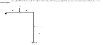
Transcribed Image Text:Assume constant El.
Either by Slope Deflection Method or by the Moment Distribution Method (max of 4 iterations/cycles only), solve for the reaction components at the supports of the rigid frame shown.
3m
P in KN
3m
4m
4m
PinkN
Expert Solution
This question has been solved!
Explore an expertly crafted, step-by-step solution for a thorough understanding of key concepts.
Step 1: Given data:
VIEW Step 2: Finding the fixed end moments:
VIEW Step 3: writing the slope deflection equations of the given frame:
VIEW Step 4: By using equilibrium equations to finding the slopes at A and B of the given frame:-
VIEW Step 5: Finding the final end moments of the given rigid frame:
VIEW Step 6: Determining the support reactions of the given rigid frame:
VIEW Solution
VIEW Step by stepSolved in 7 steps with 7 images

Knowledge Booster
Learn more about
Need a deep-dive on the concept behind this application? Look no further. Learn more about this topic, civil-engineering and related others by exploring similar questions and additional content below.Similar questions
- SOLVE STEP BY STEP The simple portico in the figure consists of a rigid lintel of length L supported by two cylindrical pillars of equal length and material. A triangular distributed load of maximum value q_0 is imposed on the lintel. Calculate the ratio between the cross sections of the columns so that buckling starts in both at the same time. Ignore the shortening of the pillars do 1 2arrow_forwardSolve the problem by the moment-area method. The beam has constant flexural rigidity EI. A simple beam AB supports two concentrated loads P at the positions shown in the figure. B C 4. 4 A support C at the midpoint of the beam is positioned at distance d below the beam before the loads are applied. Assuming that d = 12 mm, L = 5.4 m, E = 200 GPa, and I = 193 x 10° mm, calculate the magnitude of the loads P (in kN) so that the beam just touches the support at C. 163.87 x kNarrow_forwardFor the simply supported beam subjected to the loading shown, derive equations for the shear force V and the bending moment M for any location in the beam. (Place the origin at point A.) Let a=1.50 m, b=5.00 m, PA = 75kN, and PC = 90kN. Construct the shear-force and bending-moment diagrams. Calculate the reaction forces By and Dy acting on the beam. Positive values for the reactions are indicated by the directions of the red arrows shown on the free-body diagram below.arrow_forward
arrow_back_ios
arrow_forward_ios
Recommended textbooks for you

 Structural Analysis (10th Edition)Civil EngineeringISBN:9780134610672Author:Russell C. HibbelerPublisher:PEARSON
 Principles of Foundation Engineering (MindTap Cou...Civil EngineeringISBN:9781337705028Author:Braja M. Das, Nagaratnam SivakuganPublisher:Cengage Learning
 Fundamentals of Structural AnalysisCivil EngineeringISBN:9780073398006Author:Kenneth M. Leet Emeritus, Chia-Ming Uang, Joel LanningPublisher:McGraw-Hill Education
 Traffic and Highway EngineeringCivil EngineeringISBN:9781305156241Author:Garber, Nicholas J.Publisher:Cengage Learning


Structural Analysis (10th Edition)
Civil Engineering
ISBN:9780134610672
Author:Russell C. Hibbeler
Publisher:PEARSON

Principles of Foundation Engineering (MindTap Cou...
Civil Engineering
ISBN:9781337705028
Author:Braja M. Das, Nagaratnam Sivakugan
Publisher:Cengage Learning

Fundamentals of Structural Analysis
Civil Engineering
ISBN:9780073398006
Author:Kenneth M. Leet Emeritus, Chia-Ming Uang, Joel Lanning
Publisher:McGraw-Hill Education


Traffic and Highway Engineering
Civil Engineering
ISBN:9781305156241
Author:Garber, Nicholas J.
Publisher:Cengage Learning