Related questions
Question

Transcribed Image Text:### LRC Circuit Analysis
**Problem Statement:**
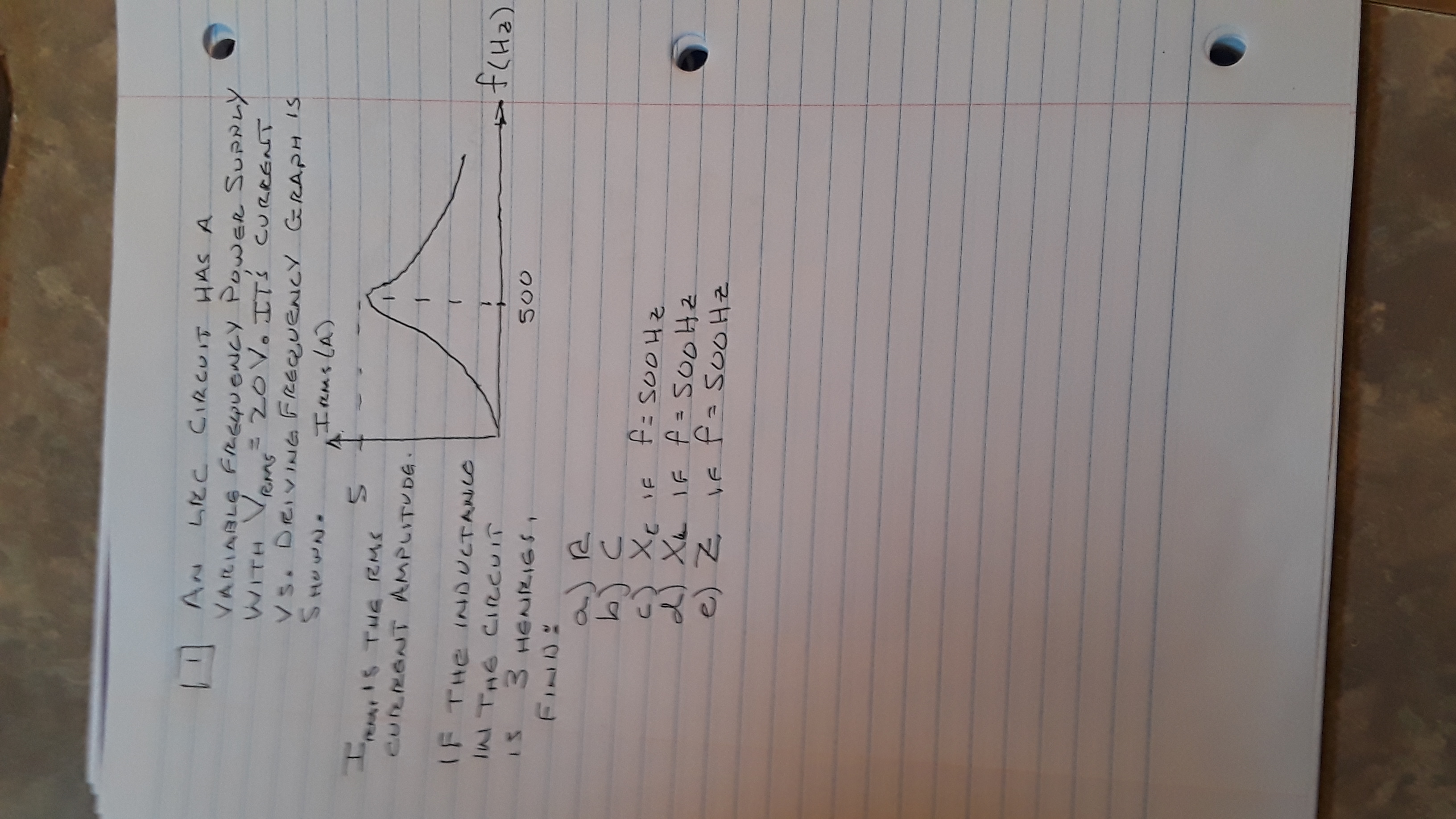
An LRC circuit has a variable frequency power supply with \( V_{rms} = 70 \, V \). Its current versus driving frequency graph is shown below.
**Graph:**
- The vertical axis represents the current \( I_{rms} (A) \).
- The horizontal axis represents the frequency \( f (Hz) \).
- The graph depicts a peak at approximately \( f = 500 \, Hz \).
**Objective:**
Determine various components of the circuit given that the inductance in the circuit is 3 henries.
**Components to Find:**
a) Resistance (\( R \))
b) Capacitance (\( C \))
c) Capacitive reactance (\( X_c \)) if \( f = 500 \, Hz \)
d) Inductive reactance (\( X_L \)) if \( f = 500 \, Hz \)
e) Impedance (\( Z \)) if \( f = 500 \, Hz \)
Use the given information and graph to calculate the requested values, taking note of peak resonant frequency and its significance in LRC circuits.
Expert Solution
arrow_forward
Step 1
Solution:
Given Values,
RMS Voltage (VRMS)=20
arrow_forward
Step 2
From the above Given Current v/s driving frequency graph:
We have,
So,
The Values of each given parameters are calculated as follows:
a) Resistance (R)
We know that,
At Resonance Condition:
So,
Here,
arrow_forward
Step 3
b) Capacitance (C):
We know that,
Capacitive Reactance
Here,
Since we know that at resonance condition:
As per the above relation, we get:

Step by stepSolved in 5 steps

Knowledge Booster

Similar questions
- Findarrow_forwarda) What driving frequency is required from a source powering a 71 microFarad capacitor, a 429 Ohm resistor, and a 209 milliHenry inductor in series so that the current is maximized? (give your answer in Hertz to 1 decimal place of precision) b) What is the phase difference between the current and voltage in a RLC series circuit with a 466 Ohm resistor, 114 microFarad capacitor, and a 234 milliHenry inductor, if the voltage source is oscillating with a frequency of 57 Hertz? (give your answer in degrees to 1 decimal place of precision)arrow_forward(a) A series RLC circuit is shown in the figure below. (170 V) sin 120 mt 5.0 Ω A Series RLC Circuit. 0000 25 mH Calculate the linear freq ency (in Hz) of the voltage source. Hz Calculate the resonance frequency. Hz Calculate the impedance at resonance. 2 400 μF Calculate the current at resonance. Aarrow_forward
- -Series RLC ciranit Amplitnde of he Voltage Source is 120V - lesistor has a valve of 802 a value of 8os2 Reactance of ne capacitor is 480e The vellage amplitade acras the capucitar is 360V (a) What is he amplitude amplinade of The curent within the cirenit? (b) What is he impedance of he circuit? (c) What are hwo possible readance valves fur he induchr and whoh ore has a smaller anqular freg vency Than resonance frequency.arrow_forwardThe figure below shows the current i and driving emf & for a series RLC circuit. "Ay Is the phase constant positive or negative? The phase constant is positive. The phase constant is negative.arrow_forward
arrow_back_ios
arrow_forward_ios