Introductory Circuit Analysis (13th Edition)
13th Edition
ISBN: 9780133923605
Author: Robert L. Boylestad
Publisher: PEARSON
expand_more
expand_more
format_list_bulleted
Question
thumb_up100%

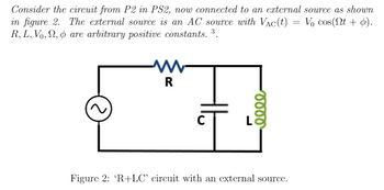
Transcribed Image Text:Consider the circuit from P2 in PS2, now connected to an external source as shown
in figure 2. The external source is an AC source with Vac(t) = V₁ cos(Nt + p).
R, L, V₁, №, & are arbitrary positive constants. ³.
R
eeee
Figure 2: 'R+LC' circuit with an external source.

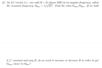
Transcribed Image Text:(f) An LC circuit (i.e. one with R = 0) shows SHO at an angular frequency, called
the resonant frequency, NRcs = 1/√LC. Find the ratio Nmax/Res. If we hold
L,C constant and vary R, do we need to increase or decrease R in order to get
max closer to Res?
Expert Solution
arrow_forward
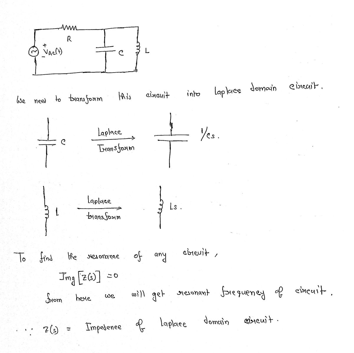
Step 1

Step by stepSolved in 3 steps with 3 images

Knowledge Booster
Similar questions
- In an AC circuit, the load has a supply voltage of 240cos(800πt+60) volts and a current of 120cos(800πt+20)mA. What is the simplest two-element parallel circuit can this load have that is equal to the total impedance. Find R,C, L.arrow_forward, A two-element series circuit has voltage V 200 / 0 V. and circuit 10 /-30° A. Determine the current which results when the resistance is reduced to (a) 25%, (b) 50% of its former value.arrow_forwardA series circuit connected across a 100-Vac source consists of a 10-Q resistor, a 5- capacitor, and a resistance R that takes 100 W anda reactance X taking 50 inductive VArs. Determine the minimum current required satisfying the above conditions.arrow_forward
- 2) a. For the circuit shown below, use the Branch Current Method to find an expression for i3 in terms of the circuit components. [ ans: i3 = -Va (R1 + R2)/ (RI R2 + R2 R3 +RI R3) ] b. Do at least two ranging checks on the answer of part a. c. Evaluate the voltage across R3 for the component values given. | ans: v = - 600 mV ] R, Values: Va = 1.0 v R1 = 100 2 R3 R2 = 200 2 R3 = 100 2 a. Use the Branch Current Method to derive an expression for v3 in the circuit below in terms of the other parameters of the circuit. (Hint: Solve for iz first.) W- R, ww | V,R, - V,(R, +R2)], V3= R3 R,R2 +R;R3+R,R3 [ans: b. Perform a units check on this equation. c. Perform one ranging check on this equation. wwarrow_forwardA testing engineer while designing a HVDC source uses several modules of circuits having six stageseach. Each stage capacitance is of 15 nF. The engineer observes that voltage is not enough with onemodule. How many such modules can he connect in cascaded fashion so that it gives best possibleperformance? Input voltage to the circuit is 100kV at 100 Hz and the load current is 1mA. Justifyyour opinion with relevant mathematical analysis.arrow_forwardExampleConsider the following electrical system as shown in the following figure. This circuit consistsof resistor, inductor and capacitor. All these electrical elements are connected in series. Theinput voltage applied to this circuit is vi and the voltage across the capacitor is the outputvoltage vo. Find vo/vi ?arrow_forward
- 1/1 By using the experiment of series connection: if the R1=50ohm, R2=100ohm and R3=150ohm.. the voltage drop at R2 is greater than R3 * and less than R1 true O false Oarrow_forwardA series circuit connected across a 100-Vac Source consists of a 10-2 resistor, a 5-2 capacitor, and a resistance R that takes 100 W and a reactance X taking 50 inductive VArs. Determine the minimum current required satisfying the above conditions.arrow_forwardc) An AC bridge in the Figure Q1c is balanced at 1 kHz and has the following components: Arm AB has 1.5 µF of capacitance in parallel with 2 kQ variable resistance Arm AC has 1 kO resistance Arm BD has 2.7 kQ variable resistance Arm CD has an unknown inductor, L. and a resistor, R, connected in series i) ii) iii) Sketch and show the components of the bridge. Classify the type of the bridge. Compute the unknown inductor, L, and resistor, R. A Z2 AC Z3 Zx D Figure Q1carrow_forward
- A coil of resistance 152 and an inductance 1H and a capacitance 15µF are connected in series across 70 N supply. The current drawn is 5A. Find the frequency of power supply. (i) A capacitor and resistor are connected in series to an ac supply of 150 V and 60Hz. The current is 5A and the power dissipated in the circuit is 70W. Calculate resistance and capacitance value. Also, draw the phasor dogram Vivo V15Pro AFTHple Cameraarrow_forwardSolve this ...with me time 35 minutesarrow_forwardIn an R-L-C series circuit a maximum current of 0.5 A is obtained by varying the value of inductance L. The supply voltage is fixed at 230 V, 50 Hz. When maximum current flows through the circuit, the voltage measured across the capacitor is 350 V. What are the values of the circuit parameters? ..arrow_forward
arrow_back_ios
SEE MORE QUESTIONS
arrow_forward_ios
Recommended textbooks for you
 Introductory Circuit Analysis (13th Edition)Electrical EngineeringISBN:9780133923605Author:Robert L. BoylestadPublisher:PEARSON
 Delmar's Standard Textbook Of ElectricityElectrical EngineeringISBN:9781337900348Author:Stephen L. HermanPublisher:Cengage Learning
 Programmable Logic ControllersElectrical EngineeringISBN:9780073373843Author:Frank D. PetruzellaPublisher:McGraw-Hill Education
 Fundamentals of Electric CircuitsElectrical EngineeringISBN:9780078028229Author:Charles K Alexander, Matthew SadikuPublisher:McGraw-Hill Education
 Electric Circuits. (11th Edition)Electrical EngineeringISBN:9780134746968Author:James W. Nilsson, Susan RiedelPublisher:PEARSON
 Engineering ElectromagneticsElectrical EngineeringISBN:9780078028151Author:Hayt, William H. (william Hart), Jr, BUCK, John A.Publisher:Mcgraw-hill Education,

Introductory Circuit Analysis (13th Edition)
Electrical Engineering
ISBN:9780133923605
Author:Robert L. Boylestad
Publisher:PEARSON

Delmar's Standard Textbook Of Electricity
Electrical Engineering
ISBN:9781337900348
Author:Stephen L. Herman
Publisher:Cengage Learning

Programmable Logic Controllers
Electrical Engineering
ISBN:9780073373843
Author:Frank D. Petruzella
Publisher:McGraw-Hill Education

Fundamentals of Electric Circuits
Electrical Engineering
ISBN:9780078028229
Author:Charles K Alexander, Matthew Sadiku
Publisher:McGraw-Hill Education

Electric Circuits. (11th Edition)
Electrical Engineering
ISBN:9780134746968
Author:James W. Nilsson, Susan Riedel
Publisher:PEARSON

Engineering Electromagnetics
Electrical Engineering
ISBN:9780078028151
Author:Hayt, William H. (william Hart), Jr, BUCK, John A.
Publisher:Mcgraw-hill Education,