Structural Analysis
6th Edition
ISBN: 9781337630931
Author: KASSIMALI, Aslam.
Publisher: Cengage,
expand_more
expand_more
format_list_bulleted
Concept explainers
Question
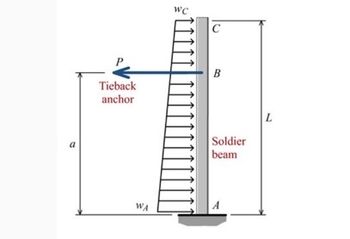
An L = 29-ft-long soldier beam is used as a key component of an earth retention system at an excavation site. The soldier beam is subjected to a soil loading that is linearly distributed from wA = 590 lb/ft to wC = 210 lb/ft, as shown. The soldier beam can be idealized as a cantilever with a fixed support at A. Added support is supplied by a tieback anchor at B, which exerts a force of P = 5800 lb on the soldier beam at a = 22 ft. Determine the horizontal deflection of the soldier beam at point C. Assume EI = 5.9 × 10⁸ lb·in.2. Deflection is positive to the left.

Transcribed Image Text:a
Tieback
anchor
WA
WC
с
Soldier
beam
A
L
Expert Solution
This question has been solved!
Explore an expertly crafted, step-by-step solution for a thorough understanding of key concepts.
Step by stepSolved in 2 steps with 2 images

Knowledge Booster
Learn more about
Need a deep-dive on the concept behind this application? Look no further. Learn more about this topic, civil-engineering and related others by exploring similar questions and additional content below.Similar questions
- 2. A dam consists of continuous flat-plat barriers whose masses are negligible. Supporting struts A, B, C and D are placed every 3 metres along the dam structure. A mud sample drawn up to the surface has a density of 1.6 Mg/m³. Determine the force in struts Cand D. All joints can be assumed to be hinged. FRESH WATER 3m B D MUD 3m A 3marrow_forward2. Solve the following problem Determine the maximum torque T that can be resisted by two shafts with a circular section of outer diameter of 100 mm. For the first shaft, the section is solid (no holes). For the second shaft, the section is hollow with an inner diameter of 75 mm. Use an allowable shear stress Tallow = 100 MPa and provide a drawing of the shear stress distribution on both sections. Rug'd max T for solid shaft Tallow = 100MP₂ diameter d loomm T hole diameter dinner = 75mm max T for hollow shaft 2D stress distributionarrow_forwardA beam simply supported on a 8 m span carries a uniformly distributed load of 30 kN/m over the middle 5 m. Using an allowable stress. fb = 120 MPa. A. Determine the most economical W shape beam, with the condition that the depth of the beam shoul not exceed 500 mm. B. What is the actual stress in the selected beam?arrow_forward
- Solve this.arrow_forwardSolve using method of consistent deformation; EI =4x10^6 KN m^2, L=3.0, Wo=20KN/marrow_forwardH.W.2. : For the base shown in figure below, estimate the elastic settlement at point (A). The base is subjected to concentric total load of 7500 kN. Assume that the base is located at 3 m below the surface of a homogenous soil which has: E, = 15 MPa, µu = 0.3 and y = 15 kN/m 4 m 2 m2 m 2 m 2 m 6 marrow_forward
- Current Attempt in Progress Two solid bars support a load P as shown. Bar (1) has a cross-sectional area of A1 = 3150 mm2 and an allowable normal stress of 175 MPa. Bar (2) has a cross-sectional area of A2 = 2900 mm2 and an allowable normal stress of 140 MPa. Assume x1 = 1.9 m, x2 = 2.9 m, y1 = 1.4 m, and y2 = 2.4 m. Determine the maximum load Pmax that can be supported by the structure without exceeding either allowable %3D %3D normal stress. y2 A (1) В W P Answer: Pmax kNarrow_forwardProblem #3 (33 points) The two 500-lb forces are parallel to the y axis and the P force is parallel to the z axis. If the allowable shear stress is 8 ksi, calculate the smallest permissible diameter of the solid shaft AE. Use the Maximum Shear Stress failure theory. 7 in P 7 in 7 in 7 in 4 in 6 in 4 in 500 Ib 500 Ibarrow_forwardCurrent Attempt in Progress Two solid bars support a load P as shown. Bar (1) has a cross-sectional area of A₁ = 4650 mm² and an allowable normal stress of 80 MPa. Bar (2) has a cross-sectional area of A2 = 2800 mm2 and an allowable normal stress of 160 MPa. Assume x₁ = 1.5 m, x₂ = 3.1 m, y₁ = 1.5 m, and y2 = 2.5 m. Determine the maximum load Pmax that can be supported by the structure without exceeding either allowable normal stress. A Answer: Pmax= (1) i B (2) C kN 1/₂arrow_forward
- 6O cm 20 20. 20cm 20 cm CrOSS - section 1. Determine the value the max Yalue g mament is 702 kN. cm gbending Stress of 2. Determine the ralue sf shean SKess of the max value g shean is 420 KN -arrow_forwardFind the expressions to calculate the maximum normal and shear stresses for a circular profile: d (diameter)= 0.30 marrow_forward
arrow_back_ios
arrow_forward_ios
Recommended textbooks for you

 Structural Analysis (10th Edition)Civil EngineeringISBN:9780134610672Author:Russell C. HibbelerPublisher:PEARSON
 Principles of Foundation Engineering (MindTap Cou...Civil EngineeringISBN:9781337705028Author:Braja M. Das, Nagaratnam SivakuganPublisher:Cengage Learning
 Fundamentals of Structural AnalysisCivil EngineeringISBN:9780073398006Author:Kenneth M. Leet Emeritus, Chia-Ming Uang, Joel LanningPublisher:McGraw-Hill Education
 Traffic and Highway EngineeringCivil EngineeringISBN:9781305156241Author:Garber, Nicholas J.Publisher:Cengage Learning


Structural Analysis (10th Edition)
Civil Engineering
ISBN:9780134610672
Author:Russell C. Hibbeler
Publisher:PEARSON

Principles of Foundation Engineering (MindTap Cou...
Civil Engineering
ISBN:9781337705028
Author:Braja M. Das, Nagaratnam Sivakugan
Publisher:Cengage Learning

Fundamentals of Structural Analysis
Civil Engineering
ISBN:9780073398006
Author:Kenneth M. Leet Emeritus, Chia-Ming Uang, Joel Lanning
Publisher:McGraw-Hill Education


Traffic and Highway Engineering
Civil Engineering
ISBN:9781305156241
Author:Garber, Nicholas J.
Publisher:Cengage Learning