Question
thumb_up100%
21

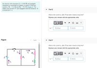
Transcribed Image Text:### Inductive Circuit Analysis
**Introduction:**
An inductor with inductance \( L = 0.400 \, \text{H} \) and negligible resistance is connected to a battery, a switch \( S \), and two resistors \( R_1 = 11.0 \, \Omega \) and \( R_2 = 15.0 \, \Omega \). The battery has an electromotive force (emf) of \( 96.0 \, \text{V} \) with negligible internal resistance. The switch \( S \) is closed at \( t = 0 \).
**Figure Explanation:**
The given circuit diagram depicts:
- A battery with emf \( \mathcal{E} = 96.0 \, \text{V} \).
- A switch \( S \) in series with resistor \( R_1 \).
- Current \( i_1 \) flows through the circuit including the battery and switch.
- Resistor \( R_1 \) with current \( i_2 \) flowing downwards.
- Resistor \( R_2 \) in series with an inductor \( L \).
- Current \( i_3 \) flows through resistor \( R_2 \) and the inductor.
**Problem Statements:**
**Part E:**
- What is the current \( i_3 \) after \( S \) has been closed a long time?
- Express your answer with the appropriate units.
**Part F:**
- What is the current \( i_1 \) after \( S \) has been closed a long time?
- Express your answer with the appropriate units.
In both parts, provide the current values and units. This problem explores the behavior of the circuit as it reaches a steady state over a considerable duration with the switch closed.

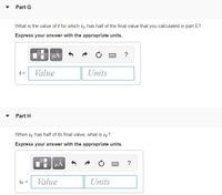
Transcribed Image Text:**Part G**
What is the value of \( t \) for which \( i_3 \) has half of the final value that you calculated in part E?
*Express your answer with the appropriate units.*
- Input box for \( t = \) with fields for "Value" and "Units".
**Part H**
When \( i_3 \) has half of its final value, what is \( i_2 \)?
*Express your answer with the appropriate units.*
- Input box for \( i_2 = \) with fields for "Value" and "Units".
Expert Solution
This question has been solved!
Explore an expertly crafted, step-by-step solution for a thorough understanding of key concepts.
This is a popular solution
Trending nowThis is a popular solution!
Step by stepSolved in 4 steps

Knowledge Booster
Similar questions
- Answerarrow_forwardProblem 4: Speed deamplifier. In the figure above on the right, block 1 of mass m1 slides along an x-axis on a frictionless floor at speed 4 m/sec.Then it undergoes a one-dimensional elastic collision with stationary block 2 of mass m2 = 2m1. Next, block 2 undergoes a one-dimensional elastic collision with stationary block 3 of mass mz = 4m1. What then is the speed of block 3? Answer: 16 m/sec or 1.78 m/sec.arrow_forward
arrow_back_ios
arrow_forward_ios