Introductory Circuit Analysis (13th Edition)
13th Edition
ISBN: 9780133923605
Author: Robert L. Boylestad
Publisher: PEARSON
expand_more
expand_more
format_list_bulleted
Concept explainers
Question

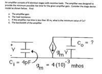
Transcribed Image Text:An amplifier consists of 8 identical stages with resistive loads. The amplifier was designed to
provide the minimum possible rise time for the given amplifier gain. Consider the stage device
model as shown below. Find:
a. The amplifier gain
b. The load resistance
c. If the amplifier rise time is less than 30 ns, what is the minimum value of Co?
d. The bandwidth of the amplifier
Io=?
4pF
4 (10) mhos
Im
-3
%3D
Expert Solution
This question has been solved!
Explore an expertly crafted, step-by-step solution for a thorough understanding of key concepts.
Step by stepSolved in 3 steps

Knowledge Booster
Learn more about
Need a deep-dive on the concept behind this application? Look no further. Learn more about this topic, electrical-engineering and related others by exploring similar questions and additional content below.Similar questions
- Consider the integrating amplifier circuit in Figure 2. Using nodal analysis, derive an expression for vout for the integrating amplifier. In the circuit in Figure 2, exchange the positions of the 0.1uF capacitor and the 5k resistor. a. Use nodal analysis to generate an expression for vout. b. Using this expression, explain what function this circuit performs on an input signal.arrow_forwardFigure 2 shows a typical BJT amplifier, with its parasitic capacitances displayed. The current gain of the transistor is B=150 and the voltage gain of the amplifier is Am =-125. The small signal resistances of the transistor are re =16 ohm and r0 = infinity, respectively. The values of resistors and capacitors in the figure are: R1 =80 kohm, R2 =20 Kohm, Rc = 2 Kohm, RE = 2 Kohm, Rs =50 W, RI=5 kohm, Cs=2 uF, Cc=2 uF, Ce =10 uF, Cbc =4 pF, Cbe = 10 pF, Cce =1 pF, Cwi = 4 pF, CWO = 9 pF, and Vcc = 20 V. a) Sketch a simplified circuit diagram of Figure 2 for high frequency analysis. b) Using the concept of "Miller effect capacitance", calculate the input and Output Miller effect capacitances of Figure 2, respectively. C) Determine the upper cut-off frequency of Figure 2 that is imposed by its input network only. d) Explain briefly the possible ways to increase the upper cut-off frequencv of this amplifier.arrow_forwardVoD +12 V For the circuit of the adjacent figure a) Given that Ip = 2.83 mA, VGS(om=-7 V and Ipss = 8 mA , find VDs and VGs.. b) If a 50 mV rms input signal is applied to the amplifier, what is the peak-to-peak output voltage? gm = 5000 µS. c) Calculate the output resistance. %3D Ro 10AF 0.1 uF R 10 L. Ra 10 MA 10kn ID= 2.83 mA, Vas (Oef)=-7V. %3Darrow_forward
- Please solve with steps, using to study. Will upvote!arrow_forwardIn an emitter-biased transistor circuit, we have collector source voltage V CC = 15 V, collector resistance RC = 3.5 kOhm, emitter voltage V_E = 4.3 V and emitter current LE = 2.1 mA. If the current gain is 150, what is the difference in emitter-collector voltage V_CE when we calculate it including the gain factor vs when it is calculated by assuming collector current LC = LE? Select one: O a. 3.35 V O b. 3.40 V OC 0.05 V O dovarrow_forwardplease solvearrow_forward
arrow_back_ios
arrow_forward_ios
Recommended textbooks for you
 Introductory Circuit Analysis (13th Edition)Electrical EngineeringISBN:9780133923605Author:Robert L. BoylestadPublisher:PEARSON
 Delmar's Standard Textbook Of ElectricityElectrical EngineeringISBN:9781337900348Author:Stephen L. HermanPublisher:Cengage Learning
 Programmable Logic ControllersElectrical EngineeringISBN:9780073373843Author:Frank D. PetruzellaPublisher:McGraw-Hill Education
 Fundamentals of Electric CircuitsElectrical EngineeringISBN:9780078028229Author:Charles K Alexander, Matthew SadikuPublisher:McGraw-Hill Education
 Electric Circuits. (11th Edition)Electrical EngineeringISBN:9780134746968Author:James W. Nilsson, Susan RiedelPublisher:PEARSON
 Engineering ElectromagneticsElectrical EngineeringISBN:9780078028151Author:Hayt, William H. (william Hart), Jr, BUCK, John A.Publisher:Mcgraw-hill Education,

Introductory Circuit Analysis (13th Edition)
Electrical Engineering
ISBN:9780133923605
Author:Robert L. Boylestad
Publisher:PEARSON

Delmar's Standard Textbook Of Electricity
Electrical Engineering
ISBN:9781337900348
Author:Stephen L. Herman
Publisher:Cengage Learning

Programmable Logic Controllers
Electrical Engineering
ISBN:9780073373843
Author:Frank D. Petruzella
Publisher:McGraw-Hill Education

Fundamentals of Electric Circuits
Electrical Engineering
ISBN:9780078028229
Author:Charles K Alexander, Matthew Sadiku
Publisher:McGraw-Hill Education

Electric Circuits. (11th Edition)
Electrical Engineering
ISBN:9780134746968
Author:James W. Nilsson, Susan Riedel
Publisher:PEARSON

Engineering Electromagnetics
Electrical Engineering
ISBN:9780078028151
Author:Hayt, William H. (william Hart), Jr, BUCK, John A.
Publisher:Mcgraw-hill Education,