Elements Of Electromagnetics
7th Edition
ISBN: 9780190698614
Author: Sadiku, Matthew N. O.
Publisher: Oxford University Press
expand_more
expand_more
format_list_bulleted
Concept explainers
Question
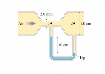
Air flows through the tube shown in (Figure 1). Assume that air is an ideal fluid. Find the air speed v1 at point 1 and v2 at point 2 and the volume flow rate.

Transcribed Image Text:Air
2.0 mm
10 cm
2.
1.0 cm
Hg
Expert Solution
This question has been solved!
Explore an expertly crafted, step-by-step solution for a thorough understanding of key concepts.
This is a popular solution
Trending nowThis is a popular solution!
Step by stepSolved in 5 steps

Knowledge Booster
Learn more about
Need a deep-dive on the concept behind this application? Look no further. Learn more about this topic, mechanical-engineering and related others by exploring similar questions and additional content below.Similar questions
- Derive the energy equation from Reynolds transport theoremarrow_forward1. A piston-cylinder is producing a viscous oil flow, which has the flow rate of Q, radius R=1.5 mm, and stroke L-5 mm. The fluid density is p = 800 kg/m³ and the viscosity is μ = 0.5 Pa-s. The pressure to drive the flow is p=6.25 Pa. a. How many non-dimensional groupings can be obtained? Derive them. b. If the flow transitions at Re = PV(2R) =2300. Is the generated flow laminar or turbulent given Q=20 mL/s? LL c. Assume the pressure gradient is uniform on the cross-section and can be calculated using OP=-. The velocity profile in the cylinder is u(r) = ax - [1-(²]. Sketch the velocity profile. Calculate the shear stress at the R² ap 2UÔI cylinder wall and label the direction. d. Calculate the flow rate Q with the velocity profile in (c).. e. If the shear stress is uniform over the cross-section, i.e. T = C, what's the pressure gradient distribution and sketch it? L L. Rarrow_forwardTranscribed Image Text:As part of a processing of biofuels, water is pumped into a circular tank with a diameter Dt. as shown in Figure Q3. The flowrate into the tank is Q₁ and the flowrate out is Q₂. When the vessel is heated, water evaporates. The average velocity at which the vapour rises across the entire tank is vevap- You may assume that water has a density of Pw, and vapour has a density of Pv. Acceleration due to gravity is g. 2₁ Vevap Q₂ => D₂ Figure Q3: Water being pumped through a heated evaporation tank. Find anexpressio for the rate of chnage of the mass of water in the tank At time t= 0 the height of water in the tank is h0. Find an expression for the height as a function of time h(t) An alarm is triggered when the pressure at the bottom of the tank exceeds P alarm. Find an expression for the time at which the alarm goes offarrow_forward
- Q1: Water is flowing from tank A to tank B as shown in the following figure. The flow is steady so that the water level in tank B does not change. Find h, in the figure. The density is constant. The flow is inviscid and irrotational. Hint: apply Bernoulli's equation between the free surface and the discharge for tanks A and B individually. Then, since the flow rate leaving tank A (and entering tank B) must equal the rate leaving tank B, these two Bernoulli's Equations can be substituted and solved for one unknown. 1 10.0 cm = 0.01 m Tank A 士 Tank B d 0.02 m Figure 1. Q1arrow_forwardIf 475mm diameter pipeline (A) conveying water splits into 2 smaller pipelines (B) and (C), 275mm and 200mm respectively in diameter. If the velocity of flow in (A) is 2.8 m/sec and the flowrate in (B) is twice that in (C), calculate the flowrate in all pipes and the velocity of flow in pipes (B) and (C).arrow_forwardCouarrow_forward
- Q6: The U-bend in the figure below is connected to a flow system by flexible hoses that transmit no force. The pipe has an ID of 3 in. Water is flowing through the pipe at a rate of 600 gal/min and density is 1000 kg/m³. The pressure at point 1 to 5 psig and at point 2 is 3 psig. What is the vertical component of the force in the support? Neglect the weight of the pipe and fluid. Flow FIGURE Vertical pipe U-bend. Flex hoses Supportarrow_forwardParvinbhaiarrow_forwardSection 1 is the image below the problemarrow_forward
arrow_back_ios
arrow_forward_ios
Recommended textbooks for you
 Elements Of ElectromagneticsMechanical EngineeringISBN:9780190698614Author:Sadiku, Matthew N. O.Publisher:Oxford University Press
 Mechanics of Materials (10th Edition)Mechanical EngineeringISBN:9780134319650Author:Russell C. HibbelerPublisher:PEARSON
 Thermodynamics: An Engineering ApproachMechanical EngineeringISBN:9781259822674Author:Yunus A. Cengel Dr., Michael A. BolesPublisher:McGraw-Hill Education
 Control Systems EngineeringMechanical EngineeringISBN:9781118170519Author:Norman S. NisePublisher:WILEY
 Mechanics of Materials (MindTap Course List)Mechanical EngineeringISBN:9781337093347Author:Barry J. Goodno, James M. GerePublisher:Cengage Learning
 Engineering Mechanics: StaticsMechanical EngineeringISBN:9781118807330Author:James L. Meriam, L. G. Kraige, J. N. BoltonPublisher:WILEY

Elements Of Electromagnetics
Mechanical Engineering
ISBN:9780190698614
Author:Sadiku, Matthew N. O.
Publisher:Oxford University Press

Mechanics of Materials (10th Edition)
Mechanical Engineering
ISBN:9780134319650
Author:Russell C. Hibbeler
Publisher:PEARSON

Thermodynamics: An Engineering Approach
Mechanical Engineering
ISBN:9781259822674
Author:Yunus A. Cengel Dr., Michael A. Boles
Publisher:McGraw-Hill Education

Control Systems Engineering
Mechanical Engineering
ISBN:9781118170519
Author:Norman S. Nise
Publisher:WILEY

Mechanics of Materials (MindTap Course List)
Mechanical Engineering
ISBN:9781337093347
Author:Barry J. Goodno, James M. Gere
Publisher:Cengage Learning

Engineering Mechanics: Statics
Mechanical Engineering
ISBN:9781118807330
Author:James L. Meriam, L. G. Kraige, J. N. Bolton
Publisher:WILEY