
Introductory Circuit Analysis (13th Edition)
13th Edition
ISBN: 9780133923605
Author: Robert L. Boylestad
Publisher: PEARSON
expand_more
expand_more
format_list_bulleted
Related questions
Question
i need the answer quickly
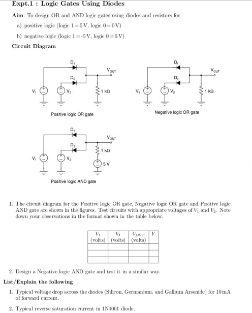

Transcribed Image Text:Expt.1 : Logic Gates Using Diodes
Aim: To design OR and AND logic gates using diodes and resistors for
a) positive logic (logic 1=5V, logic 0=0V)
b) negative logie (logic 1=-5V, logic 0 =0 V)
Circuit Diagram
Vour
Vour
1 ka
1 kn
Positive logic OR gate
Negative logic OR gate
Vaut
D.
1 kn
15V
Positive logic AND gate
1. The circuit diagram for the Positive logic OR gate, Negative logic OR gate and Positive logie
AND gate are shown in the figures. Test circuits with appropriate voltages of Vi and Va. Note
down your observations in the format shown in the table below.
VoUr
Y
(volts) (volts) (volts)
2. Design a Negative logic AND gate and test it in a similar way.
List/Explain the following
1. Typical voltage drop across the diodes (Silicon, Germanium, and Gallium Arsenide) for 10mA
of forward current.
2. Typical reverse saturation current in 1N4001 diode.
Expert Solution
This question has been solved!
Explore an expertly crafted, step-by-step solution for a thorough understanding of key concepts.

This is a popular solution

Trending nowThis is a popular solution!

Step by stepSolved in 3 steps with 2 images

Knowledge Booster

Similar questions
- Please answer with detail and how it is done. Photo is attached with the questions.arrow_forward1.a. A fiber optic cable has a minimum bend radius of 8 cm and will be mounted in an expansion loop with support messengers. How far should neighboring support messengers be placed when installing this cable?A. At least 16 cmB. Less than 16 cmC. At least 20 cmD. Exactly 20 cm 1.b. A corner pull box has conduits that are separated by 36 cm. If you install a cable in this pull box, what should the minimum bend radius be?A. At least 8 cmB. Less than 12 cmC. Less than 8 cmD. At least 12 cmarrow_forwardPlease answer this diligently. Other answers in the internet seems wrong. Please help me understand and solve this problem. I'll give a like. Thanks! Ig2sc = __________; Isc = __________; MVAsc = __________arrow_forward
- 12. A short circuit describes the condition where there's contact between theA. hot wire and the neutral wire.B. grounded conductor and the grounding wire.C. hot wire and the grounding wire.D. neutral wire and the grounded conductor. I'm not sure if it's the letter A or C, could you help me with the correct answer.arrow_forwardA cylindrical 00 AWG copper wire is coated with NEMA class B insulation. The normaloperating temperature of the wire is . What is the maximum current the wire can carry for 1second without exceeding the NEMA temperature rating?arrow_forwardIf an electrical system operates at a potential higher than 600 volts, the nonmetallic conduit must be encased in at least_of concrete. A. 1 inch B. 2 inches C. 4 inches D. 6 inchesarrow_forward
- The _______ diode used in the circuit below Your answer -OVarrow_forwardWhat is the total number of systems?arrow_forwardEstimate the length of conduit to perform the next bends. EMT will be bend using a hand bender. Provide your answer in inches (just the number) using up to 2 decimals. The picture shows two panels connected by a back-to-back 23.5" stubs EMT 3/4" 6.25 ft Parrow_forward
- The contractor is controlled by?arrow_forward4. Do some search about the functionality of Airport Metal Detectors. Explain your answer in a paragraph.arrow_forwardThe wording that I am running into with questions such as "The number of conductors required to be installed between three-way and four-way switches is " is confusing. The text is not expalining this in a way that I am understanding anything other than grounding conductor, which is optional unless I am using a metal box. So what type of "conductor" is beng discussed?arrow_forward
arrow_back_ios
arrow_forward_ios
Recommended textbooks for you
- Introductory Circuit Analysis (13th Edition)Electrical EngineeringISBN:9780133923605Author:Robert L. BoylestadPublisher:PEARSON
 Delmar's Standard Textbook Of ElectricityElectrical EngineeringISBN:9781337900348Author:Stephen L. HermanPublisher:Cengage Learning
 Programmable Logic ControllersElectrical EngineeringISBN:9780073373843Author:Frank D. PetruzellaPublisher:McGraw-Hill Education
  Fundamentals of Electric CircuitsElectrical EngineeringISBN:9780078028229Author:Charles K Alexander, Matthew SadikuPublisher:McGraw-Hill Education
 Electric Circuits. (11th Edition)Electrical EngineeringISBN:9780134746968Author:James W. Nilsson, Susan RiedelPublisher:PEARSON
 Engineering ElectromagneticsElectrical EngineeringISBN:9780078028151Author:Hayt, William H. (william Hart), Jr, BUCK, John A.Publisher:Mcgraw-hill Education,
Introductory Circuit Analysis (13th Edition)
Electrical Engineering
ISBN:9780133923605
Author:Robert L. Boylestad
Publisher:PEARSON
Delmar's Standard Textbook Of Electricity
Electrical Engineering
ISBN:9781337900348
Author:Stephen L. Herman
Publisher:Cengage Learning
Programmable Logic Controllers
Electrical Engineering
ISBN:9780073373843
Author:Frank D. Petruzella
Publisher:McGraw-Hill Education
Fundamentals of Electric Circuits
Electrical Engineering
ISBN:9780078028229
Author:Charles K Alexander, Matthew Sadiku
Publisher:McGraw-Hill Education
Electric Circuits. (11th Edition)
Electrical Engineering
ISBN:9780134746968
Author:James W. Nilsson, Susan Riedel
Publisher:PEARSON
Engineering Electromagnetics
Electrical Engineering
ISBN:9780078028151
Author:Hayt, William H. (william Hart), Jr, BUCK, John A.
Publisher:Mcgraw-hill Education,