
Introductory Circuit Analysis (13th Edition)
13th Edition
ISBN: 9780133923605
Author: Robert L. Boylestad
Publisher: PEARSON
expand_more
expand_more
format_list_bulleted
Related questions
Question
a1.Using a dc and ac voltmeter to measure the output signal from a filter cicruit, we obtain readings of 25 v dc and 1.5 V rms.Calculate the ripple of the filter output voltage.
a2. 2 a dc voltage provides 60v when the output is unloaded.When connected to a load, the output drops TO 56 V. calculate the value of voltage regulation.
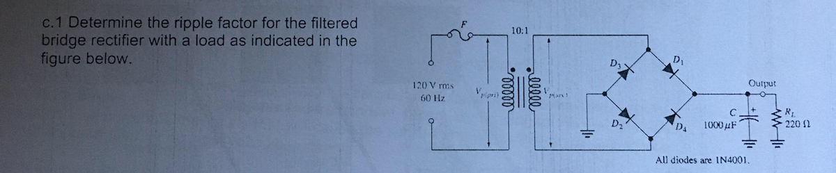

Transcribed Image Text:c.1 Determine the ripple factor for the filtered
bridge rectifier with a load as indicated in the
figure below.
10:1
D1
120 V rmis
Output
ripri
60 Hz
R
220 1
DA
1000#F
All diodes are IN4001.
ellee
Expert Solution
This question has been solved!
Explore an expertly crafted, step-by-step solution for a thorough understanding of key concepts.

Step by stepSolved in 2 steps with 1 images

Knowledge Booster


Learn more about
Need a deep-dive on the concept behind this application? Look no further. Learn more about this topic, electrical-engineering and related others by exploring similar questions and additional content below.Similar questions
- The input voltage (vin) of the following circuit is a sinusoidal signal with an amplitude of 2Vrms,consider a silicon diode.graph the output voltage ?? and the current across the resistor.arrow_forward14. A biased parallel clipper is connected to a squarewave 20VAC input.The biasing voltage of 5V has the same polarity with the Vo while the Si diode is connected in reverse and will conduct only during negative half cycle.arrow_forwardFor the given circuit below, it operates on a peak-to-peak input voltage of 347.1 V, F = 60 Hz household supply through a step- down transformer with turns N1 = 10 and N2 = 1. Silicon diodes are used with a 1 Kiloohms load. Determine the output peak voltage (in volts). D1 D2 AC Input Vsec B (source) D3 D4 Load 24.30 15.96 12.40 O 18.75arrow_forward
- Kindly solve all the parts for mearrow_forwardAn RL load (R=0.2 Ohms, L=10 mH) is controlled by a converter. The supply voltage Vs is 600V and the chopper frequency is 200 Hz. The maximum peak to peak ripple current is equal to: Select one: a. 30A b. 55A c. 90A d. 75Aarrow_forwardPlease do D, E, and Farrow_forward
arrow_back_ios
arrow_forward_ios
Recommended textbooks for you
- Introductory Circuit Analysis (13th Edition)Electrical EngineeringISBN:9780133923605Author:Robert L. BoylestadPublisher:PEARSON
 Delmar's Standard Textbook Of ElectricityElectrical EngineeringISBN:9781337900348Author:Stephen L. HermanPublisher:Cengage Learning
 Programmable Logic ControllersElectrical EngineeringISBN:9780073373843Author:Frank D. PetruzellaPublisher:McGraw-Hill Education
  Fundamentals of Electric CircuitsElectrical EngineeringISBN:9780078028229Author:Charles K Alexander, Matthew SadikuPublisher:McGraw-Hill Education
 Electric Circuits. (11th Edition)Electrical EngineeringISBN:9780134746968Author:James W. Nilsson, Susan RiedelPublisher:PEARSON
 Engineering ElectromagneticsElectrical EngineeringISBN:9780078028151Author:Hayt, William H. (william Hart), Jr, BUCK, John A.Publisher:Mcgraw-hill Education,
Introductory Circuit Analysis (13th Edition)
Electrical Engineering
ISBN:9780133923605
Author:Robert L. Boylestad
Publisher:PEARSON
Delmar's Standard Textbook Of Electricity
Electrical Engineering
ISBN:9781337900348
Author:Stephen L. Herman
Publisher:Cengage Learning
Programmable Logic Controllers
Electrical Engineering
ISBN:9780073373843
Author:Frank D. Petruzella
Publisher:McGraw-Hill Education
Fundamentals of Electric Circuits
Electrical Engineering
ISBN:9780078028229
Author:Charles K Alexander, Matthew Sadiku
Publisher:McGraw-Hill Education
Electric Circuits. (11th Edition)
Electrical Engineering
ISBN:9780134746968
Author:James W. Nilsson, Susan Riedel
Publisher:PEARSON
Engineering Electromagnetics
Electrical Engineering
ISBN:9780078028151
Author:Hayt, William H. (william Hart), Jr, BUCK, John A.
Publisher:Mcgraw-hill Education,