Introductory Circuit Analysis (13th Edition)
13th Edition
ISBN: 9780133923605
Author: Robert L. Boylestad
Publisher: PEARSON
expand_more
expand_more
format_list_bulleted
Concept explainers
Question

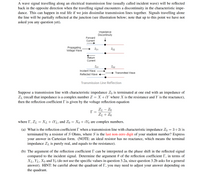
Transcribed Image Text:A wave signal travelling along an electrical transmission line (usually called incident wave) will be reflected
back in the opposite direction when the travelling signal encounters a discontinuity in the characteristic impe-
dance. This can happen in real life if we join dissimilar transmission lines together. Signals travelling alone
the line will be partially reflected at the junction (see illustration below; note that up to this point we have not
asked you any question yet).
Impedance
Discontinuity
Forward
Current
Propagating
Voltage Wave
Z01
Zo2
Return
Current
Z01
Zo2
Incident Wave
Transmitted Wave
Reflected Wave
Transmission Line Reflection
Suppose a transmission line with characteristic impedance Zo is terminated at one end with an impedance of
ZL (recall that impedance is a complex number Z = X +iY where X is the resistance and Y is the reactance),
then the reflection coefficient I' is given by the voltage reflection equation
ZL – Zo
ZL + Zo
where I, ZL = XL + iYL, and Zo
Xo + iYo are complex numbers.
(a) What is the reflection coefficient I when a transmission line with characteristic impedance Zo = 3+2i is
terminated by a resistor of S Ohms, where S is the last non-zero digit of your student number? Express
your answer in Cartesian form. (NOTE: an ideal resistor has no reactance, which means the terminal
impedance ZL is purely real, and equals to the resistance).
(b) The argument of the reflection coefficient I' can be interpreted as the phase shift in the reflected signal
compared to the incident signal. Determine the argument 0 of the reflection coefficient I', in terms of
XL, YL, Xo and Yo (do not use the specific values in question 3.2a, since question 3.2b asks for a general
answer). HINT: be careful about the quadrant of I', you may need to adjust your answer depending on
the quadrant.
Expert Solution
This question has been solved!
Explore an expertly crafted, step-by-step solution for a thorough understanding of key concepts.
This is a popular solution
Trending nowThis is a popular solution!
Step by stepSolved in 2 steps

Knowledge Booster
Learn more about
Need a deep-dive on the concept behind this application? Look no further. Learn more about this topic, electrical-engineering and related others by exploring similar questions and additional content below.Similar questions
- What will be the velocity of an em wave of the relative permittivity is 4 and relative permeability is unity?arrow_forward18.a. How does dispersion affect light pulses in an optical fiber? A. It causes total internal reflection. B. It can cause pulses to be indistinguishable. C. It causes pulses to die off as they travel down a fiber. D. It causes pulses to increase in power as they travel down a fiber. 18.b. Which of the following frequency bands do single-mode optical fibers use for communication? A. L B. C C. S 18.c. What type of cable is presently used to route phone and internet service to homes? A. Patch B. Fiber optic C. Twisted copper D. Coaxialarrow_forward
arrow_back_ios
arrow_forward_ios
Recommended textbooks for you
 Introductory Circuit Analysis (13th Edition)Electrical EngineeringISBN:9780133923605Author:Robert L. BoylestadPublisher:PEARSON
 Delmar's Standard Textbook Of ElectricityElectrical EngineeringISBN:9781337900348Author:Stephen L. HermanPublisher:Cengage Learning
 Programmable Logic ControllersElectrical EngineeringISBN:9780073373843Author:Frank D. PetruzellaPublisher:McGraw-Hill Education
 Fundamentals of Electric CircuitsElectrical EngineeringISBN:9780078028229Author:Charles K Alexander, Matthew SadikuPublisher:McGraw-Hill Education
 Electric Circuits. (11th Edition)Electrical EngineeringISBN:9780134746968Author:James W. Nilsson, Susan RiedelPublisher:PEARSON
 Engineering ElectromagneticsElectrical EngineeringISBN:9780078028151Author:Hayt, William H. (william Hart), Jr, BUCK, John A.Publisher:Mcgraw-hill Education,

Introductory Circuit Analysis (13th Edition)
Electrical Engineering
ISBN:9780133923605
Author:Robert L. Boylestad
Publisher:PEARSON

Delmar's Standard Textbook Of Electricity
Electrical Engineering
ISBN:9781337900348
Author:Stephen L. Herman
Publisher:Cengage Learning

Programmable Logic Controllers
Electrical Engineering
ISBN:9780073373843
Author:Frank D. Petruzella
Publisher:McGraw-Hill Education

Fundamentals of Electric Circuits
Electrical Engineering
ISBN:9780078028229
Author:Charles K Alexander, Matthew Sadiku
Publisher:McGraw-Hill Education

Electric Circuits. (11th Edition)
Electrical Engineering
ISBN:9780134746968
Author:James W. Nilsson, Susan Riedel
Publisher:PEARSON

Engineering Electromagnetics
Electrical Engineering
ISBN:9780078028151
Author:Hayt, William H. (william Hart), Jr, BUCK, John A.
Publisher:Mcgraw-hill Education,