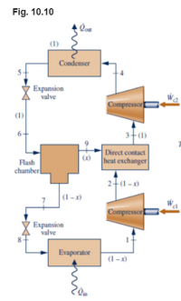
A vapor-compression refrigeration system uses the arrangement shown in Fig. 10.10 (a flash chamber and two-stage compression with intercooling between the stages). Inside the flash chamber, the liquid and vapor components separate into two streams. Refrigerant 134a is the working fluid. Saturated vapor at –28°C enters the first compressor stage. The flash chamber and direct contact heat exchanger operate at 6 bar, and the condenser pressure is 12 bar. Saturated liquid streams at 12 bar and 6 bar enter the high- and low-pressure expansion valves, respectively. If each compressor operates isentropically and the refrigerating capacity of the system is 10 tons...
draw the T/S Diagram, and determine
(a) the mass flow rate through the evaporator, in kg/s
(b) the total power input to both compressors, in kW.
(c) the coefficient of performance (COP).

Trending nowThis is a popular solution!
Step by stepSolved in 5 steps with 5 images

- Please help!!!! Refrigerant 22 enters the compressor of an ideal vapor-compression refrigeration system as saturated vapor at -30°C with a volumetric flow rate of 10 m3/min. The refrigerant leaves the condenser at 19°C, 9 bar. Determine: (a) the magnitude of the compressor power, in kW. (b) the refrigerating capacity, in tons. (c) the coefficient of performance. (d) the rate of entropy production for the cycle, in kW/K. Answer for part (a): 52 kW Answer for part (b): 59 tons Answer for part (c): 3.98 Please answer part also d! That's the part I also need. Thank you!arrow_forwardA two-stage vapor compression refrigeration system similar to the system in Fig. 10.10 of the textbook employs R134a as the working fluid. The intermediate system pressure is 6 bar, and the condenser operates at 12 bar. The high- and low- pressure expansion valves receive saturated liquid at 12 and 6 bars of pressure respectively. The first stage compressor receives saturated vapor at 10℃. Assume that the refrigeration capacity is 10 tons, and the compressors operate isentropically. Find: the coefficient of performance. the compressor power input, in kW.arrow_forwardData for steady-state operation of a vapor-compression refrigeration cycle with Refrigerant 134a as theworking fluid are given in the table below. State 1 is at the compressor inlet. The cooling capacity (i.e therate at which heat is removed from the cooled space) is 4.6 tons. 1 ton of refrigeration is equivalent to211 kJ/min. Ignoring heat transfer between the compressor and its surroundings, sketch the ?-? diagramof the cycle and determinea) the mass flow rate of the refrigerant, in kg/min.b) the isentropic compressor efficiency.c) the coefficient of performance.State ? (bar) ? (°C) ℎ (kJ/kg) ? (kJ/kg-K)arrow_forward
 Elements Of ElectromagneticsMechanical EngineeringISBN:9780190698614Author:Sadiku, Matthew N. O.Publisher:Oxford University Press
 Mechanics of Materials (10th Edition)Mechanical EngineeringISBN:9780134319650Author:Russell C. HibbelerPublisher:PEARSON
 Thermodynamics: An Engineering ApproachMechanical EngineeringISBN:9781259822674Author:Yunus A. Cengel Dr., Michael A. BolesPublisher:McGraw-Hill Education
 Control Systems EngineeringMechanical EngineeringISBN:9781118170519Author:Norman S. NisePublisher:WILEY
 Mechanics of Materials (MindTap Course List)Mechanical EngineeringISBN:9781337093347Author:Barry J. Goodno, James M. GerePublisher:Cengage Learning
 Engineering Mechanics: StaticsMechanical EngineeringISBN:9781118807330Author:James L. Meriam, L. G. Kraige, J. N. BoltonPublisher:WILEY


