
Introductory Circuit Analysis (13th Edition)
13th Edition
ISBN: 9780133923605
Author: Robert L. Boylestad
Publisher: PEARSON
expand_more
expand_more
format_list_bulleted
Related questions
Concept explainers
Question
please help
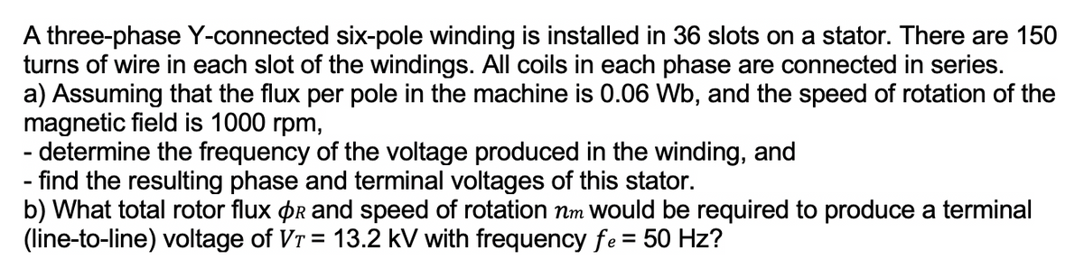

Transcribed Image Text:A three-phase Y-connected six-pole winding is installed in 36 slots on a stator. There are 150
turns of wire in each slot of the windings. All coils in each phase are connected in series.
a) Assuming that the flux per pole in the machine is 0.06 Wb, and the speed of rotation of the
magnetic field is 1000 rpm,
- determine the frequency of the voltage produced in the winding, and
- find the resulting phase and terminal voltages of this stator.
b) What total rotor flux Or and speed of rotation nm would be required to produce a terminal
(line-to-line) voltage of Vr = 13.2 kV with frequency fe = 50 Hz?
Expert Solution
This question has been solved!
Explore an expertly crafted, step-by-step solution for a thorough understanding of key concepts.

Step by stepSolved in 6 steps with 17 images

Knowledge Booster


Learn more about
Need a deep-dive on the concept behind this application? Look no further. Learn more about this topic, electrical-engineering and related others by exploring similar questions and additional content below.Similar questions
- How to convert 22 mW of power into the units of dBm?arrow_forwardVdc0 U=12 V Circuit #1 Ried V LED www Ried_series 0.05 Vdc0 U = 12 V 0,04 Circuit 0.03 0.02 0.01 RED LED GREEN LE Set current to 10 mA LED voltages Given the circuit #1 presented above, answer the following questions: BLUE_LEC Red 0.5 1) Determine the value of the V₁ (voltage forward of the LED) for the LEDS RED, VDRED GREEN, VREEN and BLUE, VOBLUES when the current through the LEDs is 10mA, 2) Is the LED in Circuit #1, connected in the way that will be lighting up or not - Justify your answer Green 3) Calculate the value of the resistance Rled in Circuit #1, to ensure that a RED LED will have a current of 10 mA 1.5 2 25 Voltage across LED (V) 4) Calculate the value of the resistance Rled in Circuit #1, to ensure that a GREEN LED will have a current of 10 mA Blue 5) Calculate the value of the resistance Rled in Circuit #1, to ensure that a Blue LED will have a current of 10 mA 6) Given three LEDs, connected in series as shown in the Circui # 2 (below), calculate the value of the…arrow_forwarda metal device box has four 12 AWG conductors, two internal clamps, and a duplex receptacle. Total voume ? Device boxsize ?arrow_forward
- energyguide labels are not required for TV's, ranges, ovens, and clothes dryers. Why do you think this is true?arrow_forwardRefer to the National Electrical Code® or the working drawings when necessary. Where applicable, responses should be written in complete sentences. For problems 1 and 2, six luminaires, similar to Style E used in the Commercial Building, are to be installed in a room that is 12 ft x 18 ft (~3.7 m x ~5.5 m) with a 9 ft (2.8 m) floor-to-ceiling height. The spacing ratio for the luminaire is 1:0. 1. The maximum distance that the luminaires can be separated and achieve uniform illuminance is ft ( m). For problems 2-5, two luminaires, 8 ft (2.5 m) and 4 ft (1.2 m) in length with dimensions as shown in Figure 15-7, are to be installed in tandem (end to end). The end of the long luminaire is to be 2 ft (600 mm) from the wall. 2. The center of the outlet box should be roughed in at ft ( m) from the wall. 3. The first support should be installed at the wall. ft ( m) from 4. The second support should be installed at from the wall. ft ( m) 5. The final support should be installed at the wall. ft…arrow_forwardNonearrow_forward
arrow_back_ios
arrow_forward_ios
Recommended textbooks for you
- Introductory Circuit Analysis (13th Edition)Electrical EngineeringISBN:9780133923605Author:Robert L. BoylestadPublisher:PEARSON
 Delmar's Standard Textbook Of ElectricityElectrical EngineeringISBN:9781337900348Author:Stephen L. HermanPublisher:Cengage Learning
 Programmable Logic ControllersElectrical EngineeringISBN:9780073373843Author:Frank D. PetruzellaPublisher:McGraw-Hill Education
  Fundamentals of Electric CircuitsElectrical EngineeringISBN:9780078028229Author:Charles K Alexander, Matthew SadikuPublisher:McGraw-Hill Education
 Electric Circuits. (11th Edition)Electrical EngineeringISBN:9780134746968Author:James W. Nilsson, Susan RiedelPublisher:PEARSON
 Engineering ElectromagneticsElectrical EngineeringISBN:9780078028151Author:Hayt, William H. (william Hart), Jr, BUCK, John A.Publisher:Mcgraw-hill Education,
Introductory Circuit Analysis (13th Edition)
Electrical Engineering
ISBN:9780133923605
Author:Robert L. Boylestad
Publisher:PEARSON
Delmar's Standard Textbook Of Electricity
Electrical Engineering
ISBN:9781337900348
Author:Stephen L. Herman
Publisher:Cengage Learning
Programmable Logic Controllers
Electrical Engineering
ISBN:9780073373843
Author:Frank D. Petruzella
Publisher:McGraw-Hill Education
Fundamentals of Electric Circuits
Electrical Engineering
ISBN:9780078028229
Author:Charles K Alexander, Matthew Sadiku
Publisher:McGraw-Hill Education
Electric Circuits. (11th Edition)
Electrical Engineering
ISBN:9780134746968
Author:James W. Nilsson, Susan Riedel
Publisher:PEARSON
Engineering Electromagnetics
Electrical Engineering
ISBN:9780078028151
Author:Hayt, William H. (william Hart), Jr, BUCK, John A.
Publisher:Mcgraw-hill Education,