
Steel Design (Activate Learning with these NEW titles from Engineering!)
6th Edition
ISBN: 9781337094740
Author: Segui, William T.
Publisher: Cengage Learning
expand_more
expand_more
format_list_bulleted
Related questions
Concept explainers
Question
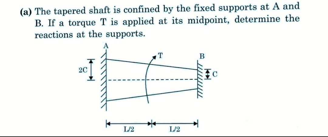

Transcribed Image Text:(a) The tapered shaft is confined by the fixed supports at A and
B. If a torque T is applied at its midpoint, determine the
reactions at the supports.
A
2C
L/2
T
L/2
B
TTTTTTTTTT
Expert Solution
This question has been solved!
Explore an expertly crafted, step-by-step solution for a thorough understanding of key concepts.

This is a popular solution

Trending nowThis is a popular solution!

Step by stepSolved in 6 steps with 7 images

Knowledge Booster


Learn more about
Need a deep-dive on the concept behind this application? Look no further. Learn more about this topic, civil-engineering and related others by exploring similar questions and additional content below.Similar questions
- A beam is part of the framing system for the floor of an office building. The floor is subjected to both dead loads and live loads. The maximum moment caused by the service dead load is 45 ft-kips, and the maximum moment for the service live load is 63 ft-kips (these moments occur at the same location on the beam and can therefore be combined). a. If load and resistance factor design is used, determine the maximum factored bending moment (required moment strength). What is the controlling AISC load combination? b. What is the required nominal moment strength for a resistance factor of 0.90? c. If allowable strength design is used, determine the required moment strength. What is the controlling AISC lead combination? d. What is the required nominal moment strength for a safety factor of 1.67?arrow_forwardCompute the nominal shear strength of an M107.5 of A572 Grad 65 steel.arrow_forwardA plate girder must be designed for the conditions shown in Figure P10.7-4. The given loads are factored, and the uniformly distributed load includes a conservative estimate of the girder weight. Lateral support is provided at the ands and at the load points. Use LRFD for that following: a. Select the, flange and web dimensions so that intermediate stiffeners will he required. Use Fy=50 ksi and a total depth of 50 inches. Bearing stiffeners will be used at the ends and at the load points, but do not proportion them. b. Determine the locations of the intermediate stiffeners, but do not proportion them.arrow_forward
arrow_back_ios
arrow_forward_ios
Recommended textbooks for you
- Steel Design (Activate Learning with these NEW ti...Civil EngineeringISBN:9781337094740Author:Segui, William T.Publisher:Cengage Learning

 Materials Science And Engineering PropertiesCivil EngineeringISBN:9781111988609Author:Charles GilmorePublisher:Cengage Learning
Steel Design (Activate Learning with these NEW ti...
Civil Engineering
ISBN:9781337094740
Author:Segui, William T.
Publisher:Cengage Learning
Materials Science And Engineering Properties
Civil Engineering
ISBN:9781111988609
Author:Charles Gilmore
Publisher:Cengage Learning