
Elements Of Electromagnetics
7th Edition
ISBN: 9780190698614
Author: Sadiku, Matthew N. O.
Publisher: Oxford University Press
expand_more
expand_more
format_list_bulleted
Related questions
Question
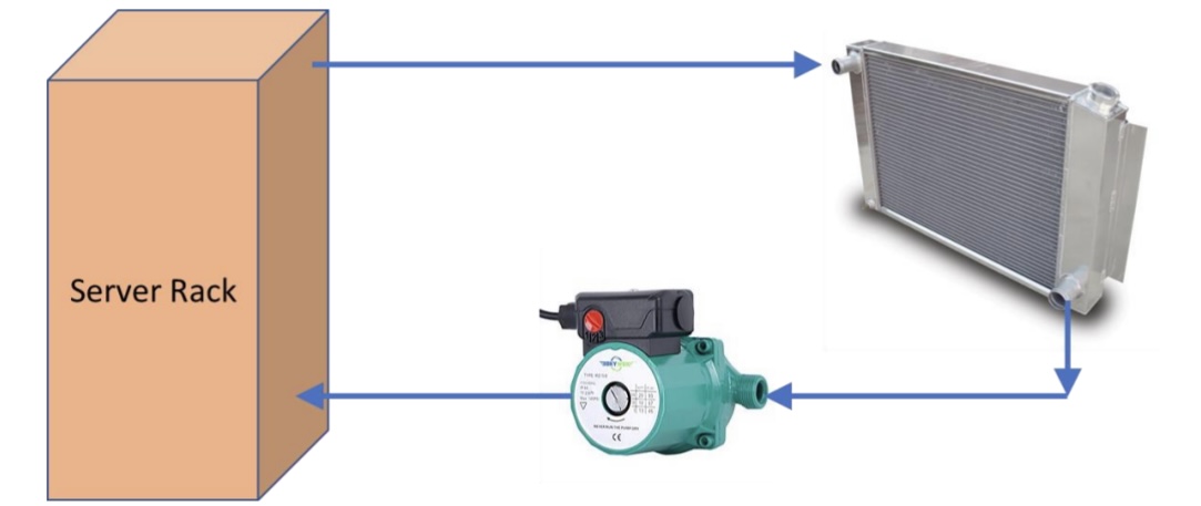

Transcribed Image Text:The image illustrates a cooling system for a server rack using a closed-loop configuration. It consists of three main components:
1. **Server Rack**: A rectangular box labeled "Server Rack," indicating where the heat is generated.
2. **Radiator**: This component is shown to the right of the server rack. It resembles a metal structure with fins, designed for heat dissipation. The radiator releases the heat transferred from the server rack.
3. **Pump**: Located below the radiator and server rack, this device circulates the coolant throughout the loop, ensuring the continuous transfer of heat away from the server rack.
**Flow of Coolant**:
- From the server rack, cooled fluid moves to the radiator, as indicated by the blue arrows pointing to the right.
- After the fluid dissipates heat in the radiator, it moves downward and enters the pump.
- The pump circulates the fluid back to the server rack, completing the cycle, as shown by the blue arrows pointing left.
This configuration maintains an efficient cooling process by circulating coolant between the server rack and the radiator.
![A system is being designed to remove heat from a server rack in a data center. The schematic provided shows the system's setup. A pump circulates water through a heat sink in the rack, removing 5000 W of heat. To prevent electronic damage, the water leaving the server rack is kept at a max temperature of 80 °C, which is considered optimal for the system. This water then circulates to a heat exchanger, modeled as a counterflow heat exchanger, where air is used to remove the heat. Air at 20 °C with a mass flow rate of 0.1 kg/s is blown through this exchanger.
The goal is to determine the optimal size for the air-to-water heat exchanger and the water's mass flow rate to minimize the system's life cycle cost. This cost, primarily from the heat exchanger's initial cost and pump energy, is given by:
\[ \text{Cost} = 45*A + 0.01*m_w^2 \]
Where:
- \( A \): area of the heat exchanger
- \( m_w \): mass flow rate of water
Additional info:
- The heat exchanger's U value is 40 W/(m²*K)
Tasks:
(a) Define the optimization problem with objective function, design variables, and constraints.
(b) Reformulate it into a single-variable optimization problem.
(c) Utilize a Fibonacci search to find optimal settings within a water mass flow rate range of 1 kg/s to 12 kg/s, accurate to 0.5 kg/s.](https://content.bartleby.com/qna-images/question/f0e69105-edad-4e40-a986-7d2af8f1b9bd/2a75fca7-2529-4889-872d-066006c60b9f/h7tx0ye_processed.jpeg)
Transcribed Image Text:A system is being designed to remove heat from a server rack in a data center. The schematic provided shows the system's setup. A pump circulates water through a heat sink in the rack, removing 5000 W of heat. To prevent electronic damage, the water leaving the server rack is kept at a max temperature of 80 °C, which is considered optimal for the system. This water then circulates to a heat exchanger, modeled as a counterflow heat exchanger, where air is used to remove the heat. Air at 20 °C with a mass flow rate of 0.1 kg/s is blown through this exchanger.
The goal is to determine the optimal size for the air-to-water heat exchanger and the water's mass flow rate to minimize the system's life cycle cost. This cost, primarily from the heat exchanger's initial cost and pump energy, is given by:
\[ \text{Cost} = 45*A + 0.01*m_w^2 \]
Where:
- \( A \): area of the heat exchanger
- \( m_w \): mass flow rate of water
Additional info:
- The heat exchanger's U value is 40 W/(m²*K)
Tasks:
(a) Define the optimization problem with objective function, design variables, and constraints.
(b) Reformulate it into a single-variable optimization problem.
(c) Utilize a Fibonacci search to find optimal settings within a water mass flow rate range of 1 kg/s to 12 kg/s, accurate to 0.5 kg/s.
Expert Solution
This question has been solved!
Explore an expertly crafted, step-by-step solution for a thorough understanding of key concepts.

This is a popular solution

Trending nowThis is a popular solution!

Step by stepSolved in 4 steps with 7 images

Knowledge Booster


Learn more about
Need a deep-dive on the concept behind this application? Look no further. Learn more about this topic, mechanical-engineering and related others by exploring similar questions and additional content below.Similar questions
- 3arrow_forwardThe figure below shows a schematic of a dual-duct system For design purposes, suppose the zones shown are two of five zones, each having identical operating design conditions. The only exhaust is the main system exhaust. The zones are to held at 75 °F db / 50% RH when the total heat gain of each one is 200,000 BTUH and the sensible heat ratio is 0.6. Outside air (OA) is 95 °F db / 40% RH and the system is designed to operate with a mass flow rate of dry air that contains 25% OA & 75% RA (return air). The hot deck provides sensible heating only, and the air exits the heating coil at 105 °F db. The cold deck is designed such that air exits the cooling coil at 50 °F db / 90 % RH. Take the pressure to be one standard atmosphere. a. Accurately sketch and label the state points on an electronic psych chart (in particular make sure that the coil is represented as a collie on the TRANE pscyh chart software you can input a coil process) b. Compute the mass flow rate (lbma/hr) through…arrow_forwardPlease show system sketches and related energy flows for all problems. 1.1 Determine the electrical power supplied to a boiler when the temperature of the entering water is 20 C and the exiting temperature is 89 C. The flow of the pressured water is 2 Kg/s. There is a negligible pressure drop through this boiler and it operates at a constant pressure of 3 bars. The specific heat is c = 4,370 J/(Kg K). There is a 1.5(105 ) W rate of heat loss from the boiler during this process to a surrounding at 293.2 k. Consider steady state conditions. 1.4 Calculate the mass flowrate of fuel (natural gas, CH4) required to heat the water flow to the conditions of problem 1.1 if the electrical heating device is replaced with a gas fired boiler. The high heating value (HHV) of the fuel is 50.02 MJ/kg. 1.5 Calculate the exergy destroyed in the process described by problem 1.4. The exergy of the fuel entering this process is 51.82 MJ/Kg. The dead state temperature is 293.2 K and pressure is 1 bar. The…arrow_forward
arrow_back_ios
arrow_forward_ios
Recommended textbooks for you
- Elements Of ElectromagneticsMechanical EngineeringISBN:9780190698614Author:Sadiku, Matthew N. O.Publisher:Oxford University Press
 Mechanics of Materials (10th Edition)Mechanical EngineeringISBN:9780134319650Author:Russell C. HibbelerPublisher:PEARSON
 Thermodynamics: An Engineering ApproachMechanical EngineeringISBN:9781259822674Author:Yunus A. Cengel Dr., Michael A. BolesPublisher:McGraw-Hill Education
  Control Systems EngineeringMechanical EngineeringISBN:9781118170519Author:Norman S. NisePublisher:WILEY
 Mechanics of Materials (MindTap Course List)Mechanical EngineeringISBN:9781337093347Author:Barry J. Goodno, James M. GerePublisher:Cengage Learning
 Engineering Mechanics: StaticsMechanical EngineeringISBN:9781118807330Author:James L. Meriam, L. G. Kraige, J. N. BoltonPublisher:WILEY
Elements Of Electromagnetics
Mechanical Engineering
ISBN:9780190698614
Author:Sadiku, Matthew N. O.
Publisher:Oxford University Press
Mechanics of Materials (10th Edition)
Mechanical Engineering
ISBN:9780134319650
Author:Russell C. Hibbeler
Publisher:PEARSON
Thermodynamics: An Engineering Approach
Mechanical Engineering
ISBN:9781259822674
Author:Yunus A. Cengel Dr., Michael A. Boles
Publisher:McGraw-Hill Education
Control Systems Engineering
Mechanical Engineering
ISBN:9781118170519
Author:Norman S. Nise
Publisher:WILEY
Mechanics of Materials (MindTap Course List)
Mechanical Engineering
ISBN:9781337093347
Author:Barry J. Goodno, James M. Gere
Publisher:Cengage Learning
Engineering Mechanics: Statics
Mechanical Engineering
ISBN:9781118807330
Author:James L. Meriam, L. G. Kraige, J. N. Bolton
Publisher:WILEY