
Structural Analysis
6th Edition
ISBN: 9781337630931
Author: KASSIMALI, Aslam.
Publisher: Cengage,
expand_more
expand_more
format_list_bulleted
Related questions
Concept explainers
Question
thumb_up100%
A square footing ( 3'×3') shown in figure. Determine the allowable resisting moment (M), if the dead load is 350 kips and live load is 450 kips and F.S = 3. Using Meyerhof Equation.
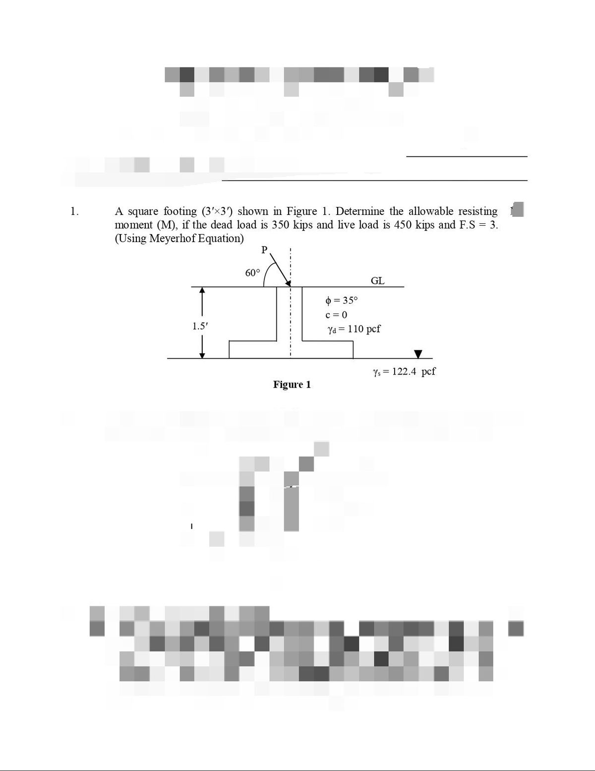

Transcribed Image Text:A square footing (3'x3') shown in Figure 1. Determine the allowable resisting
moment (M), if the dead load is 350 kips and live load is 450 kips and F.S = 3.
(Using Meyerhof Equation)
1.
P
60°
GL
0 = 35°
c = 0
1.5'
Yd = 110 pcf
Ys = 122.4 pcf
Figure 1

Transcribed Image Text:Figure 3
Table 01
Terzaghi's Bearing Capacity Factors
(For General Shear Failure)
Table 02
Bearing Capacity Factors for General Bearing Capacity Equation
Ne
N,
Ne
Ny
Ny(M) N, (v) N, (H) • N. N.
Ny{M) N, (V) N, (H)
N.
N.
0°
5.70
1.00
0.00
25
25.13
12.72
8.34
5.10
1.00
0.00
0.00
0.00
25
20.72
10.66
6.77
10.88
6.76
1°
6.00
1.10
0.01
26
27.09
14.21
9.84
1*
538
1.09
0.00
0.07
0.00
26
22.25
11.85
8.00
12.54
7.94
2°
6.30
1.22
0.04
27
29.24
15.90
11.60
2
5.63
120
0.01
0.15
0.01
27
23.94
13.20
9.46
14.47
9.32
3°
6.62
1.35
0.06
28
31.61
17.81
13.70
3"
5.90
131
0.02
0.24
0.02
28
25.80
14.72
11.19
16.72
10.94
4°
6.97
1.49
0.10
29
34.24
19.98
16.18
4"
6.19
1.43
0.04
0.34
0.05
29
27.86
16.44
13.24
19.34
1284
5°
7.34
1.64
0.14
30
37.16
2246
19.13
6.49
1.7
0.07
0.45
0.07
30
30.14
18.40
15.67
22.40
15.07
6°
7.73
1.81
0.20
31
40.41
25.28
22.65
6"
681
1.72
0.11
0.57
0.11
31
32.67
20.63
18.56
25.99
17.69
7°
8.15
2.00
0.27
32
44.04
28.52
26.87
7.16
188
0.15
0.71
0.16
32
35.49
23.18
22.02
30.21
20.79
8°
8.60
2.21
0.35
33
48.09
32.23
31.94
7.53
2.06
0.21
0.86
0.22
33
38.64
26.09
26.17
35.19
24.44
34
35
9°
9.09
2.44
0.44
52.64
36.50
38.04
7.92
225
0.28
1.03
0.30
34
42.16
29.44
31.15
41.06
28.77
10
9.60
2.69
0.56
57.75
41.44
45.41
10
834
2.47
0.37
1.22
0.39
35
46.12
3330
37.15
48.03
33.92
11
10.16
2.98
0.69
36°
63.53
47.16
54.36
2.71
0.47
0.50
36
50.59
37.75
44.43
56.31
40.05
11
1.44
12
10.76
3.29
0.85
37
70.07
53.80
65.27
12
9.28
2.97
0.60
1.69
0.63
37
55.63
42.92
53.27
66.19
47.38
13
11.41
3.63
1.04
38
77.50
61.55
78.61
13
981
3.26
0.74
1.97
0.78
38
61.35
48.93
64.07
78.02
56.17
14
12.11
4.02
1.26
39
85.97
70.61
95.03
14
10.37
3.59
0.92
2.29
0.97
39
67.87
55.96
7733
92.25
66.76
15
10.98
3.94
1.13
2.65
1.18
40
75.31
64.20
93.69
109.41
79.54
15
12.86
4.45
1.52
40
95.66
81.27
115.31
16
11.63
434
1.37
3.06
1.43
41
83.86
73.90
113.99
130.21
95.05
16°
13.68
4.92
1.82
41
106.81
93.85
140.51
17
1234
4.77
1.66
3.53
1.73
42
93.71
85.37
13932
155.54
113.96
17°
14.56
5.45
2.18
42
119.67 108.75
171.99
18
13.10
5.26
2.00
4.07
2.08
43
105.11
99.01
17114
186.53
137.10
18
15.52
6.04
2.59
43°
134.58
126.50 211.56
19
13.93
5.80
2.40
4.68
2.48
44
118.37 115.31
21141
224.64
165.58
19
16.56
6.70
3.07
44
151.95
147.74
261.60
20
14.83
6.40
2.87
5,39
2.95
45
133.87
13487
262.74 271.75
200.81
20°
17.69
7.44
3.64
45°
172.29
173.29 325.34
21
1581
7.07
3.42
6.20
3.50
46
152.10
158.50
328.73
330,34
244.65
196.22 204.19
224.55 241.80
21°
18.92
8.26
4.31
46°
407.11
16.88
7.82
4.07
7.13
173.64
187.21
403.66
299.52
22
4.13
47
414.33
22
20.27
9.19
5.09
47
512.84
23
18.05
866
4.82
8.20
4.88
48
199.26
222.30
526.46
496.00
368.67
23°
21.75
10.23
6.00
48°
258.29
287.86
650.67
24
19.32
9.60
5,72
9,44
5.75
674.92
456.41
49
229.93
265.50
613.15
24
23.36
11.40
7.08
49
298.72
344.64
831.99
Expert Solution
This question has been solved!
Explore an expertly crafted, step-by-step solution for a thorough understanding of key concepts.

This is a popular solution

Trending nowThis is a popular solution!

Step by stepSolved in 3 steps

Knowledge Booster


Learn more about
Need a deep-dive on the concept behind this application? Look no further. Learn more about this topic, civil-engineering and related others by exploring similar questions and additional content below.Similar questions
- Q1: The pad footing is used to support the axial loads 8000 lb and bending moment 2000 lb. ft. Determine the intensities W1 and W2 of the distributed loading acting on the base of footing for equilibrium. Steel Column FIKED COMMECTION 2000 b SASE PLATE -RC Foobng W2 W1 40 inarrow_forward13.2 Design a square single footing to support the given square column loads. Design for moments, shear, load transfer, dowel length, and development lengths for footing main bars. Choose adequate bars and spacings. (Assume d=h-4.5 in. for all problems.) Number с Column (in.) 20×20 Column bars 12 no. 9 Dead Load (K) 245 Live 9s Load (K) (Ksi) (Ksf) 159 3 6 H (ft) 7 Part Answers h (in.) 23 L (ft) 9arrow_forward
Recommended textbooks for you
 Structural Analysis (10th Edition)Civil EngineeringISBN:9780134610672Author:Russell C. HibbelerPublisher:PEARSON
 Principles of Foundation Engineering (MindTap Cou...Civil EngineeringISBN:9781337705028Author:Braja M. Das, Nagaratnam SivakuganPublisher:Cengage Learning
 Fundamentals of Structural AnalysisCivil EngineeringISBN:9780073398006Author:Kenneth M. Leet Emeritus, Chia-Ming Uang, Joel LanningPublisher:McGraw-Hill Education
 Traffic and Highway EngineeringCivil EngineeringISBN:9781305156241Author:Garber, Nicholas J.Publisher:Cengage Learning
Structural Analysis (10th Edition)
Civil Engineering
ISBN:9780134610672
Author:Russell C. Hibbeler
Publisher:PEARSON
Principles of Foundation Engineering (MindTap Cou...
Civil Engineering
ISBN:9781337705028
Author:Braja M. Das, Nagaratnam Sivakugan
Publisher:Cengage Learning
Fundamentals of Structural Analysis
Civil Engineering
ISBN:9780073398006
Author:Kenneth M. Leet Emeritus, Chia-Ming Uang, Joel Lanning
Publisher:McGraw-Hill Education
Traffic and Highway Engineering
Civil Engineering
ISBN:9781305156241
Author:Garber, Nicholas J.
Publisher:Cengage Learning