
Introductory Circuit Analysis (13th Edition)
13th Edition
ISBN: 9780133923605
Author: Robert L. Boylestad
Publisher: PEARSON
expand_more
expand_more
format_list_bulleted
Related questions
Question
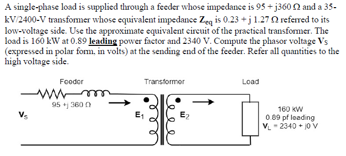

Transcribed Image Text:A single-phase load is supplied through a feeder whose impedance is 95 + j360 2 and a 35-
kV/2400-V transformer whose equivalent impedance Zeq is 0.23 +j 1.27 N referred to its
low-voltage side. Use the approximate equivalent circuit of the practical transformer. The
load is 160 kW at 0.89 leading power factor and 2340 V. Compute the phasor voltage Vs
(expressed in polar form, in volts) at the sending end of the feeder. Refer all quantities to the
high voltage side.
Feeder
Transformer
Load
95 +j 360 0
160 kW
Vs
E1
E2
0.89 pf leading
VL = 2340 + jo Vv
Expert Solution
This question has been solved!
Explore an expertly crafted, step-by-step solution for a thorough understanding of key concepts.

This is a popular solution

Trending nowThis is a popular solution!

Step by stepSolved in 3 steps with 9 images

Follow-up Questions
Read through expert solutions to related follow-up questions below.
Follow-up Question
How do I compute voltage at the high voltage terminal of the transformer
Solution
by Bartleby Expert
Follow-up Question

Transcribed Image Text:K
= 95.94 -36.88° A
Therefore the load volt
Vload - Load Zload
(95.94 -36.88° A) (5 236.87⁰ (2)
479.7 Z-0.01° V
And the line losses are given by;
Ploss = (line) ² Ruine
= (9.594 A)²(0.18 (2)
16.7 W
7| Page
a.
b.
4.0 TRANSFORMERS PDF
Notice that by stepping up the transmission voltage of the power system, the transmission losses
have been reduced by a factor of 90. In addition, the voltage at the load dropped significantly in
the system with transformers compared to the system without transformers.
a L
Exercise:
95 + £360
A single-phase load is supplied through a 35-kV feeder whose impedance is
2 and a 35-kV:2400-V transformer whose equivalent impedance is (0.23 +1.27) 22 referred
to its low-voltage side. The load is 160 kW at 0.89 leading power factor and 2340 V.
Compute the voltage at the high-voltage terminals of the transformer.
Compute the voltage at the sending end of the feeder.
Compute the power and reactive power input at the sending end of the feeder.
Main components of a power transformer
The Figure below illustrates a cut-away view of an oil-filled transformer.
The main components of the transformer are as follows:
Core. Provides a route for the magnetic flux and supports the low-voltage and high voltage
windings.
Low-voltage winding. It has fewer turns compared with the high voltage windings. Its conductor
has a large diameter because it carries more current.
High-voltage winding. It has a larger number of turns, and its conductor has a smaller diameter
than the low-voltage winding conductor. The high-voltage winding is usually wound around the
low-voltage winding (only cooling ducts and insulation separate the windings). This is done to
minimize the voltage stress on the core insulation.
Tank. Houses the windings, core, and oil. It must be strong enough to withstand the gas pressures
and electromagnetic forces that could develop when a fault occurs.
Oil. It is a good-quality mineral oil. It provides insulation between the windings, core, and
transformer tank. It also removes the heat generated. The oil is specially refined, and it must be
free from impurities such as water, inorganic acid, alkali, sulphur, vegetable and mineral oil.
Note: Some transformers use askarel, which is a nonflammable insulating and cooling medium
instead of insulating oil. It gives good fire protection, which is a significant advantage when the
transformer is located inside a building. However, askarel contains polychlorinated biphenals
(PCBS). They have been linked to cancer-causing substances.
Therefore, they have been banned. Most industries are now in the process of replacing transformers
containing askarel with dry-type transformers or transformers
containing mineral oil.
Thermometer. Measures the oil temperature and initiates an alarm when the temperature exceeds
the alarm set point.
Low/high-voltage bushing. Ceramic bushing that carries the low/high-voltage conductor and
incula
insulates it from the tank. The high-voltage bushing is usually filled with oil to enhance the heat
removal capability.
8| Page
Low/high-voltage connection. Connects the low/high-voltage conductor to the circuit.
Conservator tank. It contains oil and has the capability of absorbing the swell of the oil when it
becomes hot.
7
Solution
by Bartleby Expert
Follow-up Questions
Read through expert solutions to related follow-up questions below.
Follow-up Question
How do I compute voltage at the high voltage terminal of the transformer
Solution
by Bartleby Expert
Follow-up Question
Transcribed Image Text:K
= 95.94 -36.88° A
Therefore the load volt
Vload - Load Zload
(95.94 -36.88° A) (5 236.87⁰ (2)
479.7 Z-0.01° V
And the line losses are given by;
Ploss = (line) ² Ruine
= (9.594 A)²(0.18 (2)
16.7 W
7| Page
a.
b.
4.0 TRANSFORMERS PDF
Notice that by stepping up the transmission voltage of the power system, the transmission losses
have been reduced by a factor of 90. In addition, the voltage at the load dropped significantly in
the system with transformers compared to the system without transformers.
a L
Exercise:
95 + £360
A single-phase load is supplied through a 35-kV feeder whose impedance is
2 and a 35-kV:2400-V transformer whose equivalent impedance is (0.23 +1.27) 22 referred
to its low-voltage side. The load is 160 kW at 0.89 leading power factor and 2340 V.
Compute the voltage at the high-voltage terminals of the transformer.
Compute the voltage at the sending end of the feeder.
Compute the power and reactive power input at the sending end of the feeder.
Main components of a power transformer
The Figure below illustrates a cut-away view of an oil-filled transformer.
The main components of the transformer are as follows:
Core. Provides a route for the magnetic flux and supports the low-voltage and high voltage
windings.
Low-voltage winding. It has fewer turns compared with the high voltage windings. Its conductor
has a large diameter because it carries more current.
High-voltage winding. It has a larger number of turns, and its conductor has a smaller diameter
than the low-voltage winding conductor. The high-voltage winding is usually wound around the
low-voltage winding (only cooling ducts and insulation separate the windings). This is done to
minimize the voltage stress on the core insulation.
Tank. Houses the windings, core, and oil. It must be strong enough to withstand the gas pressures
and electromagnetic forces that could develop when a fault occurs.
Oil. It is a good-quality mineral oil. It provides insulation between the windings, core, and
transformer tank. It also removes the heat generated. The oil is specially refined, and it must be
free from impurities such as water, inorganic acid, alkali, sulphur, vegetable and mineral oil.
Note: Some transformers use askarel, which is a nonflammable insulating and cooling medium
instead of insulating oil. It gives good fire protection, which is a significant advantage when the
transformer is located inside a building. However, askarel contains polychlorinated biphenals
(PCBS). They have been linked to cancer-causing substances.
Therefore, they have been banned. Most industries are now in the process of replacing transformers
containing askarel with dry-type transformers or transformers
containing mineral oil.
Thermometer. Measures the oil temperature and initiates an alarm when the temperature exceeds
the alarm set point.
Low/high-voltage bushing. Ceramic bushing that carries the low/high-voltage conductor and
incula
insulates it from the tank. The high-voltage bushing is usually filled with oil to enhance the heat
removal capability.
8| Page
Low/high-voltage connection. Connects the low/high-voltage conductor to the circuit.
Conservator tank. It contains oil and has the capability of absorbing the swell of the oil when it
becomes hot.
7
Solution
by Bartleby Expert
Knowledge Booster


Learn more about
Need a deep-dive on the concept behind this application? Look no further. Learn more about this topic, electrical-engineering and related others by exploring similar questions and additional content below.Similar questions
Recommended textbooks for you
- Introductory Circuit Analysis (13th Edition)Electrical EngineeringISBN:9780133923605Author:Robert L. BoylestadPublisher:PEARSON
 Delmar's Standard Textbook Of ElectricityElectrical EngineeringISBN:9781337900348Author:Stephen L. HermanPublisher:Cengage Learning
 Programmable Logic ControllersElectrical EngineeringISBN:9780073373843Author:Frank D. PetruzellaPublisher:McGraw-Hill Education
  Fundamentals of Electric CircuitsElectrical EngineeringISBN:9780078028229Author:Charles K Alexander, Matthew SadikuPublisher:McGraw-Hill Education
 Electric Circuits. (11th Edition)Electrical EngineeringISBN:9780134746968Author:James W. Nilsson, Susan RiedelPublisher:PEARSON
 Engineering ElectromagneticsElectrical EngineeringISBN:9780078028151Author:Hayt, William H. (william Hart), Jr, BUCK, John A.Publisher:Mcgraw-hill Education,
Introductory Circuit Analysis (13th Edition)
Electrical Engineering
ISBN:9780133923605
Author:Robert L. Boylestad
Publisher:PEARSON
Delmar's Standard Textbook Of Electricity
Electrical Engineering
ISBN:9781337900348
Author:Stephen L. Herman
Publisher:Cengage Learning
Programmable Logic Controllers
Electrical Engineering
ISBN:9780073373843
Author:Frank D. Petruzella
Publisher:McGraw-Hill Education
Fundamentals of Electric Circuits
Electrical Engineering
ISBN:9780078028229
Author:Charles K Alexander, Matthew Sadiku
Publisher:McGraw-Hill Education
Electric Circuits. (11th Edition)
Electrical Engineering
ISBN:9780134746968
Author:James W. Nilsson, Susan Riedel
Publisher:PEARSON
Engineering Electromagnetics
Electrical Engineering
ISBN:9780078028151
Author:Hayt, William H. (william Hart), Jr, BUCK, John A.
Publisher:Mcgraw-hill Education,