
Elements Of Electromagnetics
7th Edition
ISBN: 9780190698614
Author: Sadiku, Matthew N. O.
Publisher: Oxford University Press
expand_more
expand_more
format_list_bulleted
Related questions
Question
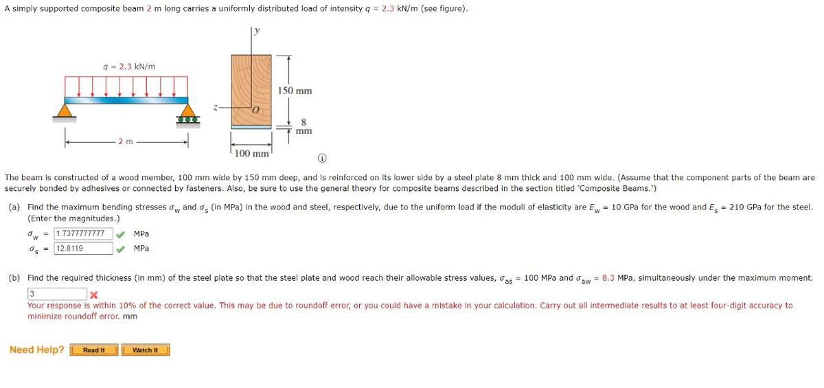

Transcribed Image Text:A simply supported composite beam 2 m long carries a uniformly distributed load of intensity q = 2.3 kN/m (see figure).
q= 2.3 kN/m
2 m
ow = 1.7377777777 ✔ MPa
12.8119
MPa
The beam is constructed of a wood member, 100 mm wide by 150 mm deep, and is reinforced on its lower side by a steel plate 8 mm thick and 100 mm wide. (Assume that the component parts of the beam are
securely bonded by adhesives or connected by fasteners. Also, be sure to use the general theory for composite beams described in the section titled 'Composite Beams.')
Need Help?
100 mm
(a) Find the maximum bending stresses ow and a (in MPa) in the wood and steel, respectively, due to the uniform load if the moduli of elasticity are E = 10 GPa for the wood and E = 210 GPa for the steel.
(Enter the magnitudes.)
150 mm
Read It
8
mm
(b) Find the required thickness (in mm) of the steel plate so that the steel plate and wood reach their allowable stress values, as = 100 MPa and aw = 8.3 MPa, simultaneously under the maximum moment.
X
Your response is within 10% of the correct value. This may be due to roundoff error, or you could have a mistake in your calculation. Carry out all intermediate results to at least four-digit accuracy to
minimize roundoff error. mm
Watch It
Expert Solution
This question has been solved!
Explore an expertly crafted, step-by-step solution for a thorough understanding of key concepts.

Step by stepSolved in 4 steps with 2 images

Knowledge Booster


Learn more about
Need a deep-dive on the concept behind this application? Look no further. Learn more about this topic, mechanical-engineering and related others by exploring similar questions and additional content below.Similar questions
- A laminated plastic beam of square cross section is built up by gluing together three strips, each 10 mm x 30 mm in cross section (see figure). The beam has a total weight of 3.6 N and is simply supported with span length L = 360 mm. Considering the weight of the beam (q), calculate the maximum permissible CCW moment M that may be placed at the right support.a. The allowable shear stress in the glued joints is 0.3 MPa.b. The allowable bending stress in the plastic is 8 MPaarrow_forwardA simply supported steel beam of length L = 16 ft is loaded with two forces PA = 350 lbf and PB = 100 lbf, as shown in the figure. The loads are applied at a = 4 ft and b = 8 ft from the left end. Using singularity functions, find the minimum moment of inertia needed to support the loads without deflecting more than 0.5 in at the mid-span. y PA PB Lii b a A B C The minimum moment of inertia needed to support the loads without deflecting more than 0.5 in at the mid-span is 3.47 in4.arrow_forwardPlease don't provide handwritten solution.....arrow_forward
- A simply supported wood beam of rectangular cross section and span length 1.2 m carries a concentrated load P at midspan in addition to its own weight (see figure). The cross section has width 140 mm and height 240 mm. The weight density of the wood is 5,4 kN/m3Calculate the maximum permissible value of the load P if (a) the allowable bending stress is MPa and (b) the allowable shear stress is 0,8 MPaarrow_forward5.10-8 A bridge girder AB on a simple span of length L = 14 m supports a distributed load of max- imum intensity q at mid-span and minimum intensity 412 at supports A and B that includes the weight of the girder (see figure). The girder is constructed of three plates welded to form the cross section shown. Determine the maximum permissible load q based upon (a) an allowable bending stress oallow = 110 MPa and (b) an allowable shear stress 7 low = 50 MPa. 450 mm 32 mm B L= 14 m - 16 mm- 1800 mm 32 mm 450 mmarrow_forwardA simply supported wood beam of length L = 11 ft carries a concentrated load P at midspan, as shown. The cross-sectional dimensions of the beam are b = 7 in. and h = 13 in. If the allowable shear strength of the wood is 125 psi, determine the maximum load P that may be applied at midspan. Neglect the effects of the beam's self-weight. A Answer: P = 2 P B lb 12 L C X Z b harrow_forward
- 2) 5.5-5 A rectangular beam ABC (L = 15 ft; h= 12 in.) has simple supports at A and B and an overhang from B to C. A uniform load with intensity q = 150 lb/ft is applied to the beam and the section modulus S = 50 in³. Determine the maximum stress max in the beam. (Clue: Check for local maximum and minimum in bending moment diagram. The maximum magnitude will produce maximum stress). PROBLEM 5.5-5 MH17 B 10 ft 5 ftarrow_forwardH.W 4 A simple beam on a 10 ft span supports a uniform load of intensity 800 lb/ft (see figure). The beam consists of a wood member (4 in. X 11.5 in. in cross section) that is reinforced by 0.25 in. thick steel plates on top and bottom. The moduli of elasticity for the steel and wood are E, 30 × 10° psi and E, = 1.5 × 10° psi, respectively. Calculate the maximum bending stresses o, in the steel plates and o,, in the wood member due to the uniform load. y 0.25 in. 800 lb/ft 11.5 in. 0.25 in. 10 ft 4 in. FIGURE 4arrow_forward5.8-6) A cantilever beam of length L = 2 m sup- ports a load P = 8.0 kN (see figure). The beam is made of wood with cross-sectional dimensions 120 mm X 200 mm. Calculate the shear stresses due to the load P at points located 25 mm, 50 mm, 75 mm, and 100 mm from the top surface of the beam. From these results, plot a graph showing the distribution of shear stresses from top to bottom of the beam. P = 8.0 kN 200 mm L = 2 m 120 mm PROBLEM 5.8-6arrow_forward
- A cantilever beam of rectangular cross section is subjected to a concentrated load P = 150 kN acting at the free end (see Figure 1). The beam has width b = 80 mm. and height h = 260 mm. Point A is located at distance c = 0.5 m from the free end and distance d = 220 mm. from the bottom of the beam. a) Using Mohr's circle, calculate the principal stresses oi and o2 and the maximum shear stress Tmax at point A. b) Show these stresses on sketches of properly oriented elements. A•arrow_forwardQ3) A circular bar of 25mm diameter is formed into a semicircular arch and loaded as shown in the figure. Determine the maximum bending stress. Assume that the flexure formula for straight beams is applicable. 200KN 100KN R=1.5m 230°arrow_forwardA beam is loaded as shown in the figure. The length 1-20 in. and the load locations are a=10 in. and b= 15 in. The beam is steel with E = 30 Mpsi. The magnitude of the concentrated force is F= 500 lb and the distributed load is 50 lb/in. The dimensions of the beam cross-section are h = 5 and t = 2. You will be finding the deflection and slope at the end of the beam. a b 1 W Farrow_forward
arrow_back_ios
SEE MORE QUESTIONS
arrow_forward_ios
Recommended textbooks for you
- Elements Of ElectromagneticsMechanical EngineeringISBN:9780190698614Author:Sadiku, Matthew N. O.Publisher:Oxford University Press
 Mechanics of Materials (10th Edition)Mechanical EngineeringISBN:9780134319650Author:Russell C. HibbelerPublisher:PEARSON
 Thermodynamics: An Engineering ApproachMechanical EngineeringISBN:9781259822674Author:Yunus A. Cengel Dr., Michael A. BolesPublisher:McGraw-Hill Education
  Control Systems EngineeringMechanical EngineeringISBN:9781118170519Author:Norman S. NisePublisher:WILEY
 Mechanics of Materials (MindTap Course List)Mechanical EngineeringISBN:9781337093347Author:Barry J. Goodno, James M. GerePublisher:Cengage Learning
 Engineering Mechanics: StaticsMechanical EngineeringISBN:9781118807330Author:James L. Meriam, L. G. Kraige, J. N. BoltonPublisher:WILEY
Elements Of Electromagnetics
Mechanical Engineering
ISBN:9780190698614
Author:Sadiku, Matthew N. O.
Publisher:Oxford University Press
Mechanics of Materials (10th Edition)
Mechanical Engineering
ISBN:9780134319650
Author:Russell C. Hibbeler
Publisher:PEARSON
Thermodynamics: An Engineering Approach
Mechanical Engineering
ISBN:9781259822674
Author:Yunus A. Cengel Dr., Michael A. Boles
Publisher:McGraw-Hill Education
Control Systems Engineering
Mechanical Engineering
ISBN:9781118170519
Author:Norman S. Nise
Publisher:WILEY
Mechanics of Materials (MindTap Course List)
Mechanical Engineering
ISBN:9781337093347
Author:Barry J. Goodno, James M. Gere
Publisher:Cengage Learning
Engineering Mechanics: Statics
Mechanical Engineering
ISBN:9781118807330
Author:James L. Meriam, L. G. Kraige, J. N. Bolton
Publisher:WILEY