Elements Of Electromagnetics
7th Edition
ISBN: 9780190698614
Author: Sadiku, Matthew N. O.
Publisher: Oxford University Press
expand_more
expand_more
format_list_bulleted
Question

Transcribed Image Text:**2. Analysis of Shear Strain in a Two-Dimensional Stress System**
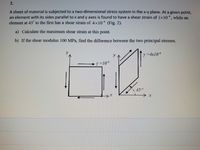
A sheet of material is subjected to a two-dimensional stress system in the x-y plane. At a given point, an element with its sides parallel to the x and y axes is found to have a shear strain of \(1 \times 10^{-4}\), while an element at 45° to the first has a shear strain of \(4 \times 10^{-4}\) (Fig. 2).
**Questions:**
a) Calculate the maximum shear strain at this point.
b) If the shear modulus is \(100 \, \text{MPa}\), find the difference between the two principal stresses.
**Explanation of Figures:**
- The first graph illustrates a rectangular element aligned with the x and y axes, showing a shear strain \(\gamma = 10^{-4}\).
- The second graph depicts a rhombus-shaped element oriented at a 45° angle to the original element, showing an increased shear strain \(\gamma ' = 4 \times 10^{-4}\).
The diagrams illustrate the changes in shear strain experienced by the material when oriented differently relative to the primary axis. This visual representation is essential for understanding stress transformations in materials subject to multidirectional forces.
Expert Solution
This question has been solved!
Explore an expertly crafted, step-by-step solution for a thorough understanding of key concepts.
This is a popular solution
Trending nowThis is a popular solution!
Step by stepSolved in 2 steps with 2 images

Knowledge Booster
Similar questions
- 2.6 The truss ABC shown in the figure supports a horizontal load P₁ = 9 kN and a vertical load P₂ = 18 kN. Both bars have cross-sectional area A = 1,290 mm² and are made of steel with E= 210 GPa. a) Determine the strain energy U₁ of the truss when the load P₁ acts alone (P₂ = 0). b) Determine the strain energy U₂ when the load P2 acts alone (P₁ = 0). c) Determine the strain energy U when both loads act simultaneously. 813 mm 1524 mm P₁ = 9 kN P₂ = 18 kNarrow_forwardThe principle planes are two planes which are separated by 90° where the principle stresses occur. Under which condition do the principle stresses and associated principle planes occur? O O O O When the shear stress is not zero When the normal stress in the y-direction is zero Don't Know When the normal stress in x-direction is zero When the shear stress is zeroarrow_forwardI need helparrow_forward
Recommended textbooks for you
 Elements Of ElectromagneticsMechanical EngineeringISBN:9780190698614Author:Sadiku, Matthew N. O.Publisher:Oxford University Press
 Mechanics of Materials (10th Edition)Mechanical EngineeringISBN:9780134319650Author:Russell C. HibbelerPublisher:PEARSON
 Thermodynamics: An Engineering ApproachMechanical EngineeringISBN:9781259822674Author:Yunus A. Cengel Dr., Michael A. BolesPublisher:McGraw-Hill Education
 Control Systems EngineeringMechanical EngineeringISBN:9781118170519Author:Norman S. NisePublisher:WILEY
 Mechanics of Materials (MindTap Course List)Mechanical EngineeringISBN:9781337093347Author:Barry J. Goodno, James M. GerePublisher:Cengage Learning
 Engineering Mechanics: StaticsMechanical EngineeringISBN:9781118807330Author:James L. Meriam, L. G. Kraige, J. N. BoltonPublisher:WILEY

Elements Of Electromagnetics
Mechanical Engineering
ISBN:9780190698614
Author:Sadiku, Matthew N. O.
Publisher:Oxford University Press

Mechanics of Materials (10th Edition)
Mechanical Engineering
ISBN:9780134319650
Author:Russell C. Hibbeler
Publisher:PEARSON

Thermodynamics: An Engineering Approach
Mechanical Engineering
ISBN:9781259822674
Author:Yunus A. Cengel Dr., Michael A. Boles
Publisher:McGraw-Hill Education

Control Systems Engineering
Mechanical Engineering
ISBN:9781118170519
Author:Norman S. Nise
Publisher:WILEY

Mechanics of Materials (MindTap Course List)
Mechanical Engineering
ISBN:9781337093347
Author:Barry J. Goodno, James M. Gere
Publisher:Cengage Learning

Engineering Mechanics: Statics
Mechanical Engineering
ISBN:9781118807330
Author:James L. Meriam, L. G. Kraige, J. N. Bolton
Publisher:WILEY