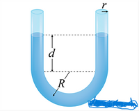
A section of uniform pipe is bent into an upright U shape and partially filled with water, which can then oscillate back and forth in simple harmonic motion. The inner radius of the pipe is r = 0.024 m. The radius of curvature of the curved part of the U is R = 0.23 m. When the water is not oscillating, the depth of the water in the straight sections is d = 0.37 m.
Enter an expression for the mass of water in the tube, in terms of the defined quantities and the density of water, ρ. Use the approximation r << R.
Calculate the mass of the water, in kilograms. Take ρ = 1000 kg/m3.
Enter an expression for the force constant of the U-shaped column of water when displaced from equilibrium, in terms of the defined quantities, ρ, and g. This constant is analogous to the spring constant in Hooke’s law.
Find the value of the force constant, in newtons per meter. Take ρ = 1000 kg/m3 and g = 9.81 m/s2.
Calculate the period of oscillation, in seconds.

Trending nowThis is a popular solution!
Step by stepSolved in 4 steps

- and w2 and Two parallel traveling plane waves have different angular frequencies @1 pressure amplitudes P₁ and P₂. (a) Show that the instantaneous energy density %; at a point in space varies between (P₁ + P₂)² / poc² and (P₁ – P₂)² / poc². (b) Show that the total energy density & at the point averages to the sum of the individual energy densities of each wave alone. Hint: Let the averaging time be much greater than 2πT/|w1 - w₂|.arrow_forwardProblem Consider a cylindrical pipe of length L and diameter D = 2R. The angle that the axis of the pipe forms with the vertical direction is a. Assume that when the fluid enters the pipe its velocity is uniform (i.e., it has the same value over the entire cross-section of the pipe) and equal to U in the axial direction. In the radial and angular directions, the velocity is zero. So, it is: 2 =0: v(r, 0, 2) = Ue, (1.1) Here v is the fluid velocity and e, is a vector of unit magnitude parallel to the coordinate axis z; furthermore, we have assumed that the pipe inlet is located at z = 0. Near the entrance of the pipe, the velocity profile varies in the axial direction. But after a certain entrance length, the profile becomes fully developed, no longer changing with z. The evolution of the velocity profile is sketched in Fig. 1, where, for clarity, the pipe inclination is not shown. The entrance length is denoted by L.. For z > L., the fluid velocity is no longer a function of the axial…arrow_forwardA sample is subjected to a hydraulic gradient of dhlax = 01 cm/cm in the x clirection and a flux qy of 0.001 cm/s in the y direction in response to this gradient (there is no gradient in the y direction). The same sample is then subjected to a hydraulic gradient of @hidy = 0.01 cm/cm in the y direction and a flux qx is measured in the x direction in response to this gradient (there is no gradient in the x direction). What is the magnitude of the flux qx in response to @hdy!arrow_forward
- Use the Shell Balance approach for Momentum conservation, create a sketch of a control volume in Cartesian coordinates, and indicate all fluxes and forces in your sketch. Use this Shell Balance to derive the following Momentum conservation equations. Ju x-motion: p(u + v) = -x + +μl ax ax y-motion: p(u Əv + v) = - 3² - ду μ (a²u Əx² a²v əx² J²u + + Bx ay², +372) + Byarrow_forwardDerive an expression for the shear stress acting on the top plate Tw. Q' is the flow rate per unit width (i.e. has units of m^2/s). Express Q' in terms of Tw. When the flow rate per unit width is Q'=1.2*(10^-4) m^2/s, the gap between the plates is 5mm, he device estimates the shear stress at the top wall to be -0.05 Pa. Estimate the viscosity of the fluid. When the tests are repeated for blood ample, different estimates of viscosity are found for different flowrates. What does this tell you about the viscosity of the flow? Use appropriate terminology. As the pressure gradient is increased, at a certain point the measurements cease to be reliable. Using knowledge of fluid mechanics, give a possible reasonfor this. Use appropriate terminology.arrow_forwardA water diffuser is constructed like that in the figure below. Diffuser wall 2 m Flow Entrance 7 m Exit The volumetric flow rate at the entrance (per meter depth into the plane of the image) is 14.0 m2/s and the pressure difference Pexit - Pentrance = 350 kPa. What is the expansion angle in degrees? iarrow_forward
 Elements Of ElectromagneticsMechanical EngineeringISBN:9780190698614Author:Sadiku, Matthew N. O.Publisher:Oxford University Press
 Mechanics of Materials (10th Edition)Mechanical EngineeringISBN:9780134319650Author:Russell C. HibbelerPublisher:PEARSON
 Thermodynamics: An Engineering ApproachMechanical EngineeringISBN:9781259822674Author:Yunus A. Cengel Dr., Michael A. BolesPublisher:McGraw-Hill Education
 Control Systems EngineeringMechanical EngineeringISBN:9781118170519Author:Norman S. NisePublisher:WILEY
 Mechanics of Materials (MindTap Course List)Mechanical EngineeringISBN:9781337093347Author:Barry J. Goodno, James M. GerePublisher:Cengage Learning
 Engineering Mechanics: StaticsMechanical EngineeringISBN:9781118807330Author:James L. Meriam, L. G. Kraige, J. N. BoltonPublisher:WILEY


