
Elements Of Electromagnetics
7th Edition
ISBN: 9780190698614
Author: Sadiku, Matthew N. O.
Publisher: Oxford University Press
expand_more
expand_more
format_list_bulleted
Related questions
Concept explainers
Question
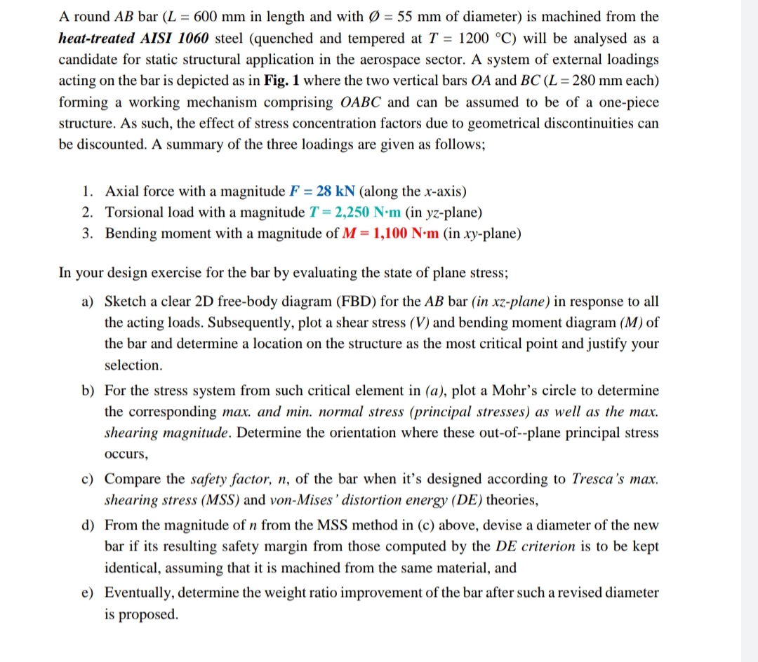

Transcribed Image Text:A round AB bar (L = 600 mm in length and with Ø = 55 mm of diameter) is machined from the
heat-treated AISI 1060 steel (quenched and tempered at T = 1200 °C) will be analysed as a
candidate for static structural application in the aerospace sector. A system of external loadings
acting on the bar is depicted as in Fig. 1 where the two vertical bars OA and BC (L= 280 mm each)
forming a working mechanism comprising OABC and can be assumed to be of a one-piece
structure. As such, the effect of stress concentration factors due to geometrical discontinuities can
be discounted. A summary of the three loadings are given as follows;
1. Axial force with a magnitude F = 28 kN (along the x-axis)
2. Torsional load with a magnitude T = 2,250 N•m (in yz-plane)
3. Bending moment with a magnitude of M = 1,100 N•m (in xy-plane)
In your design exercise for the bar by evaluating the state of plane stress;
a) Sketch a clear 2D free-body diagram (FBD) for the AB bar (in xz-plane) in response to all
the acting loads. Subsequently, plot a shear stress (V) and bending moment diagram (M) of
the bar and determine a location on the structure as the most critical point and justify your
selection.
b) For the stress system from such critical element in (a), plot a Mohr's circle to determine
the corresponding max. and min. normal stress (principal stresses) as well as the max.
shearing magnitude. Determine the orientation where these out-of--plane principal stress
occurs,
c) Compare the safety factor, n, of the bar when it's designed according to Tresca's max.
shearing stress (MSS) and von-Mises' distortion energy (DE) theories,
d) From the magnitude of n from the MSS method in (c) above, devise a diameter of the new
bar if its resulting safety margin from those computed by the DE criterion is to be kept
identical, assuming that it is machined from the same material, and
e) Eventually, determine the weight ratio improvement of the bar after such a revised diameter
is proposed.

Transcribed Image Text:T = 2,250 N m
F = 28 kN
Ø = 55 mm
M, = 1,100 N-m
280 mm
Fig. 1. System of stress acting on OABC structural component
ww 009
Expert Solution
This question has been solved!
Explore an expertly crafted, step-by-step solution for a thorough understanding of key concepts.

Step by stepSolved in 7 steps with 3 images

Knowledge Booster


Learn more about
Need a deep-dive on the concept behind this application? Look no further. Learn more about this topic, mechanical-engineering and related others by exploring similar questions and additional content below.Similar questions
- Try One scene 13 of 13 Bar properties 800 mm Determine the internal forces and normal A1 500 mm? stresses in bars (1) and (2). (+ = (2) tension, compression) - = E, 80 GPa %D 470 mm 350 mm? Also, determine the deflection of the rigid bar in the x direction at C. (+= right, = left) A2 = E, 80 GPa - = 45 kN 630 mm (1) F1 53.289 kNX 1000 mm 470 mm F2 15.576 kNX X 106.578 MPAX 02 44.5 MPAX Try One VC 3.118 mmX 1st 2nd 3rd Enter attemptarrow_forward5. (a) (b) (c) Koo D d An Aluminium alloy (6061-T6) circular tube (Fig.Q5) used for vehicle fittings is under axial compression. The tube has a length L = 5m, outer diameter D = 65mm and inner diameter d = 55mm. The Young's modulus of Aluminium alloy 6061-T6 is E= 68.9 GPa and yield strength ay = 276 MPa. Determine the buckling load with the Euler formula, assuming the tube to be pin-jointed at the two ends Determine the buckling load with the Euler formula, assuming the tube to be fixed at the two ends Assuming the tube to be pin-jointed at both ends, determine the length of the tube, below which the Euler formula is no longer valid Fig.Q5 L-arrow_forwardat question A=110 MPa B=-60 MPa M=145N.marrow_forward
arrow_back_ios
arrow_forward_ios
Recommended textbooks for you
- Elements Of ElectromagneticsMechanical EngineeringISBN:9780190698614Author:Sadiku, Matthew N. O.Publisher:Oxford University Press
 Mechanics of Materials (10th Edition)Mechanical EngineeringISBN:9780134319650Author:Russell C. HibbelerPublisher:PEARSON
 Thermodynamics: An Engineering ApproachMechanical EngineeringISBN:9781259822674Author:Yunus A. Cengel Dr., Michael A. BolesPublisher:McGraw-Hill Education
  Control Systems EngineeringMechanical EngineeringISBN:9781118170519Author:Norman S. NisePublisher:WILEY
 Mechanics of Materials (MindTap Course List)Mechanical EngineeringISBN:9781337093347Author:Barry J. Goodno, James M. GerePublisher:Cengage Learning
 Engineering Mechanics: StaticsMechanical EngineeringISBN:9781118807330Author:James L. Meriam, L. G. Kraige, J. N. BoltonPublisher:WILEY
Elements Of Electromagnetics
Mechanical Engineering
ISBN:9780190698614
Author:Sadiku, Matthew N. O.
Publisher:Oxford University Press
Mechanics of Materials (10th Edition)
Mechanical Engineering
ISBN:9780134319650
Author:Russell C. Hibbeler
Publisher:PEARSON
Thermodynamics: An Engineering Approach
Mechanical Engineering
ISBN:9781259822674
Author:Yunus A. Cengel Dr., Michael A. Boles
Publisher:McGraw-Hill Education
Control Systems Engineering
Mechanical Engineering
ISBN:9781118170519
Author:Norman S. Nise
Publisher:WILEY
Mechanics of Materials (MindTap Course List)
Mechanical Engineering
ISBN:9781337093347
Author:Barry J. Goodno, James M. Gere
Publisher:Cengage Learning
Engineering Mechanics: Statics
Mechanical Engineering
ISBN:9781118807330
Author:James L. Meriam, L. G. Kraige, J. N. Bolton
Publisher:WILEY