Introductory Circuit Analysis (13th Edition)
13th Edition
ISBN: 9780133923605
Author: Robert L. Boylestad
Publisher: PEARSON
expand_more
expand_more
format_list_bulleted
Concept explainers
Question

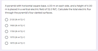
Transcribed Image Text:A pyramid with horizontal square base, 6.00 m on each side, and a height of 4.00
m is placed in a vertical electric field of 52.0 N/C. Calculate the total electric flux
through the pyramid's four slanted surfaces.
O 2130 (N-m^2)/c
O 1930 (N-m^2)/c
O 1730 (N m^2)/C
O 1970 (N m^2)/C
O 1870 (N m^2)/C
Expert Solution
This question has been solved!
Explore an expertly crafted, step-by-step solution for a thorough understanding of key concepts.
This is a popular solution
Trending nowThis is a popular solution!
Step by stepSolved in 2 steps with 3 images

Knowledge Booster
Learn more about
Need a deep-dive on the concept behind this application? Look no further. Learn more about this topic, electrical-engineering and related others by exploring similar questions and additional content below.Similar questions
- 12:04 M 9 G A O Ritesh Sah Active Now Corsider an solated negaive pont charge. What can we say about the electric feld around the charge? O the electric feid points radialy ind towaids the charge in three dinensions O the electric field points radally cutward amay from the charge in two dmensions O the ectric feld points radialy outward awy rom the charge in three dimensions he clectric field points radially inward towards the charge in two dimensions ypehere to sach More Editarrow_forwardQUESTION 4 The figure below shows a periodic voltage waveform. v (V) 4 15 18 20 t (ms) 13 -3 Determine the peak-to-peak value of the waveform. O 6 V 12 V 18 V O 9 Varrow_forwardG colin kaepernarrow_forwardHello can you please provide an explanation on how to solve this problem?arrow_forwardVSF=11.69×10-9×100+1.8663=3.0353 V how come need to times 10^9?arrow_forwardWaveform Generator RED CLIP BLACK CLIP R1 C1 1kQ 100μF Figure 3: Breadboard circuit. GND 7. Measure the value of R1: 8. Measure the value of C1: Wave Gen Wave Gen GND GND + GND GND For High Level O For Low I Level τ: R1: R1 1kQ C1: R1 1kΩ 카 GND Figure 4: Circuit behaviour. The circuits in Figure 4 show the expected behaviour of the RC circuit. When the waveform voltage level is high, the capacitor charges through R1. When the waveform voltage is low, the capacitor discharges through resistor R1. It is important to note that the switches in Figure 4 do not exist inside the instrument. They are an analogy to the circuit behaviour. 6. Calculate the T for this circuit: 11 GND C1 100μF C1 100μFarrow_forwardarrow_back_iosarrow_forward_ios
Recommended textbooks for you
 Introductory Circuit Analysis (13th Edition)Electrical EngineeringISBN:9780133923605Author:Robert L. BoylestadPublisher:PEARSON
 Delmar's Standard Textbook Of ElectricityElectrical EngineeringISBN:9781337900348Author:Stephen L. HermanPublisher:Cengage Learning
 Programmable Logic ControllersElectrical EngineeringISBN:9780073373843Author:Frank D. PetruzellaPublisher:McGraw-Hill Education
 Fundamentals of Electric CircuitsElectrical EngineeringISBN:9780078028229Author:Charles K Alexander, Matthew SadikuPublisher:McGraw-Hill Education
 Electric Circuits. (11th Edition)Electrical EngineeringISBN:9780134746968Author:James W. Nilsson, Susan RiedelPublisher:PEARSON
 Engineering ElectromagneticsElectrical EngineeringISBN:9780078028151Author:Hayt, William H. (william Hart), Jr, BUCK, John A.Publisher:Mcgraw-hill Education,

Introductory Circuit Analysis (13th Edition)
Electrical Engineering
ISBN:9780133923605
Author:Robert L. Boylestad
Publisher:PEARSON

Delmar's Standard Textbook Of Electricity
Electrical Engineering
ISBN:9781337900348
Author:Stephen L. Herman
Publisher:Cengage Learning

Programmable Logic Controllers
Electrical Engineering
ISBN:9780073373843
Author:Frank D. Petruzella
Publisher:McGraw-Hill Education

Fundamentals of Electric Circuits
Electrical Engineering
ISBN:9780078028229
Author:Charles K Alexander, Matthew Sadiku
Publisher:McGraw-Hill Education

Electric Circuits. (11th Edition)
Electrical Engineering
ISBN:9780134746968
Author:James W. Nilsson, Susan Riedel
Publisher:PEARSON

Engineering Electromagnetics
Electrical Engineering
ISBN:9780078028151
Author:Hayt, William H. (william Hart), Jr, BUCK, John A.
Publisher:Mcgraw-hill Education,