
Elements Of Electromagnetics
7th Edition
ISBN: 9780190698614
Author: Sadiku, Matthew N. O.
Publisher: Oxford University Press
expand_more
expand_more
format_list_bulleted
Related questions
Question
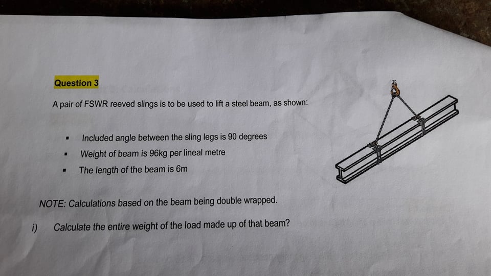

Transcribed Image Text:Question 3
A pair of FSWR reeved slings is to be used to lift a steel beam, as shown:
Included angle between the sling legs is 90 degrees
Weight of beam is 96kg per lineal metre
The length of the beam is 6m
NOTE: Calculations based on the beam being double wrapped.
i) Calculate the entire weight of the load made up of that beam?
Expert Solution
This question has been solved!
Explore an expertly crafted, step-by-step solution for a thorough understanding of key concepts.

Step by stepSolved in 3 steps

Knowledge Booster


Learn more about
Need a deep-dive on the concept behind this application? Look no further. Learn more about this topic, mechanical-engineering and related others by exploring similar questions and additional content below.Similar questions
- Design a timber beam (S4S) made from soutiiem pine for the given load in the figure belowarrow_forward2. Design a timber beam (S4S) made of Douglas fir to support the load shown below. 500 lbs/ft Ju 12'-0arrow_forward1) A long span open-web steel joist with a span of 70 feet is required to support a floor. The joists are spaced at 3.5 ft apart, the dead load is 15 lb/ft² (not including the self weight), the live load is 80 lb/ft? and the live load deflection is limited to L/360 (which is that used to determine the live load limit - in red/light - based on deflection in the SJI catalogue tables and those limits must be multiplied by 1.5 if L/240 is used). Using the LRFD table provided, select the most economical joist that can be used considering the self weight. The lighter values are the limiting unfactored live load. (Note: longer spans that can support the load can also be used.)arrow_forward
- If the "I" value of beam cross section is 6,400,000 mm and the maximum distance from the neutral axis of the cross section to the top and bottom edges of the beam cross section is 139 mm, what is the section modulus of the beam? Note: Give your answer in mm3 Note: Do NOT include units in your answer. Answer:arrow_forwardPlease draw a complete free body diagram. (A handwritten solution would be greatly appreciated)arrow_forwardNeeds Complete solutionarrow_forward
- Please help. Written on paper not typed on computer please. Need help on all questions. Please include all units, steps to the problem and information such as its direction or if it is in compression or tension. Thx.arrow_forwardIn the following cantilevered beam impact configuration pictured in Fig. 1, Determine: 1. The value of the equivalent spring K. 2. The values of the maximum impact force Fmax for weight heights ranging between h = 0 to 2 m. 3. Plot the maximum impact force Fmax as a function of the weight height h. 4. Plot the maximum force Fmax versus the maximum spring displacement Smaxwhen the weight height varies between h = 0 to 2 m. The beam has a resctangular cross section area. E = 70 GPa a = 10 cm b = 2 cm L = 1 m M = 5 kg g= 9.81 m/s² b of tat M h = 0-2 m K L Fig. 1 Cantilevered beamarrow_forwardRequired information Problem 09.034 - Fixed-fixed beam with an applied moment at the midpoint - DEPENDENT MULTI-PART PROBLEM - ASSIGN ALL PARTS Consider the beam and the loading shown. NOTE: This is a multi-part question. Once an answer is submitted, you will be unable to return to this part. A Mo B Problem 09.034.b - Draw the bending moment diagram Draw the bending-moment diagram for the beam and loading shown. (Please upload your response/solution using the controls below.)arrow_forward
- You can assume that each shaded cell is 1m x 1m square. Forces are applied at either the top edge, middle, or bottom edge of the beam. A. Circle the beams which have equivalent loading to the top beam. Please give a brief explaning to learn why. Thank you!arrow_forwardAs the same total load becomes evenly distributed over larger portions of a simple span, the maximum bending moment in the beam will Increase Decrease Remain constant No answer text provided.arrow_forward
arrow_back_ios
arrow_forward_ios
Recommended textbooks for you
- Elements Of ElectromagneticsMechanical EngineeringISBN:9780190698614Author:Sadiku, Matthew N. O.Publisher:Oxford University Press
 Mechanics of Materials (10th Edition)Mechanical EngineeringISBN:9780134319650Author:Russell C. HibbelerPublisher:PEARSON
 Thermodynamics: An Engineering ApproachMechanical EngineeringISBN:9781259822674Author:Yunus A. Cengel Dr., Michael A. BolesPublisher:McGraw-Hill Education
  Control Systems EngineeringMechanical EngineeringISBN:9781118170519Author:Norman S. NisePublisher:WILEY
 Mechanics of Materials (MindTap Course List)Mechanical EngineeringISBN:9781337093347Author:Barry J. Goodno, James M. GerePublisher:Cengage Learning
 Engineering Mechanics: StaticsMechanical EngineeringISBN:9781118807330Author:James L. Meriam, L. G. Kraige, J. N. BoltonPublisher:WILEY
Elements Of Electromagnetics
Mechanical Engineering
ISBN:9780190698614
Author:Sadiku, Matthew N. O.
Publisher:Oxford University Press
Mechanics of Materials (10th Edition)
Mechanical Engineering
ISBN:9780134319650
Author:Russell C. Hibbeler
Publisher:PEARSON
Thermodynamics: An Engineering Approach
Mechanical Engineering
ISBN:9781259822674
Author:Yunus A. Cengel Dr., Michael A. Boles
Publisher:McGraw-Hill Education
Control Systems Engineering
Mechanical Engineering
ISBN:9781118170519
Author:Norman S. Nise
Publisher:WILEY
Mechanics of Materials (MindTap Course List)
Mechanical Engineering
ISBN:9781337093347
Author:Barry J. Goodno, James M. Gere
Publisher:Cengage Learning
Engineering Mechanics: Statics
Mechanical Engineering
ISBN:9781118807330
Author:James L. Meriam, L. G. Kraige, J. N. Bolton
Publisher:WILEY