Introductory Circuit Analysis (13th Edition)
13th Edition
ISBN: 9780133923605
Author: Robert L. Boylestad
Publisher: PEARSON
expand_more
expand_more
format_list_bulleted
Concept explainers
Question

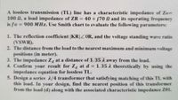
Transcribed Image Text:A lossless transmission (TL) line has a characteristic impedance of Zo=
100 2, a load impedance of ZR =
is fo = 900 MHz. Use Smith chart to evaluate the following parameters:
40 + j70 N and its operating frequency
1. The reflection coefficient |KR|Z OR, and the voltage standing wave ratio
(VSWR).
2. The distance from the load to the nearest maximum and minimum voltage
positions (in meter).
3. The impedance Za at a distance of 1.35 A away from the load.
4. Confirm your result for Za at d = 1.35 A theoretically by using the
impedance equation for lossless TL.
5. Design a series 2/4 transformer that satisfying matching of this TL with
this load. In your design, find the nearest position of this transformer
from the load (d) along with the associated characteristic impedance Z01.
Expert Solution
This question has been solved!
Explore an expertly crafted, step-by-step solution for a thorough understanding of key concepts.
This is a popular solution
Trending nowThis is a popular solution!
Step by stepSolved in 4 steps

Knowledge Booster
Learn more about
Need a deep-dive on the concept behind this application? Look no further. Learn more about this topic, electrical-engineering and related others by exploring similar questions and additional content below.Similar questions
- Question 7 A Full explain this question very fast solution sent mearrow_forwardA lossless transmission line (TL) has a characteristic impedance of Zo= 250 N, a load impedance of ZR = 125 – j150 N and its operating frequency is fo Smith chart to evaluate the following parameters: 150 MHz. Use 1) The load admittance YR. 2) The reflection coefficient [Kr|ZOR 3) The voltage standing wave ratio (VSWR). Then calculate the maximum and minimum impedance in this TL, (Zmax and Zmin). 4) The distance from load to the nearest maximum (dmax) and minimum voltage positions (dmin) (in meter). 5) Find Zd at a distance away from a load by d= 3.3 2. Then calculate Zd using TL equation.arrow_forward1. Matching of a transmission line with a characteristic impedance (Zo) and a load impedance (ZR) can be obtained when (a) ZR=0.5ZO (b) ZR-2Z0 (c) ZR-Zo (d) ZR=0 2. Standing wave ratio (S) for a short circuit load connected to a transmission line is equal to (a) S=0 (b) S=-1 (c) S= Infinity (d) S=1 3. Any transmission line repeats its impedance, voltage, and current characteristics every (Where n-0, 1, 2, 3....etc.) (b) nλ/3 (a) nλ/2 (c) ni/5 (d) nλ/6 4. In smith chart, moving in the clockwise direction means moving a) From load to generator b) From generator to load 5. In Crank diagram, moving in the clockwise direction from the load to the source can be evaluated using the formula a) +j2Bd b)-j3Bx c) -j2Bd d)-j2Bxarrow_forward
Recommended textbooks for you
 Introductory Circuit Analysis (13th Edition)Electrical EngineeringISBN:9780133923605Author:Robert L. BoylestadPublisher:PEARSON
 Delmar's Standard Textbook Of ElectricityElectrical EngineeringISBN:9781337900348Author:Stephen L. HermanPublisher:Cengage Learning
 Programmable Logic ControllersElectrical EngineeringISBN:9780073373843Author:Frank D. PetruzellaPublisher:McGraw-Hill Education
 Fundamentals of Electric CircuitsElectrical EngineeringISBN:9780078028229Author:Charles K Alexander, Matthew SadikuPublisher:McGraw-Hill Education
 Electric Circuits. (11th Edition)Electrical EngineeringISBN:9780134746968Author:James W. Nilsson, Susan RiedelPublisher:PEARSON
 Engineering ElectromagneticsElectrical EngineeringISBN:9780078028151Author:Hayt, William H. (william Hart), Jr, BUCK, John A.Publisher:Mcgraw-hill Education,

Introductory Circuit Analysis (13th Edition)
Electrical Engineering
ISBN:9780133923605
Author:Robert L. Boylestad
Publisher:PEARSON

Delmar's Standard Textbook Of Electricity
Electrical Engineering
ISBN:9781337900348
Author:Stephen L. Herman
Publisher:Cengage Learning

Programmable Logic Controllers
Electrical Engineering
ISBN:9780073373843
Author:Frank D. Petruzella
Publisher:McGraw-Hill Education

Fundamentals of Electric Circuits
Electrical Engineering
ISBN:9780078028229
Author:Charles K Alexander, Matthew Sadiku
Publisher:McGraw-Hill Education

Electric Circuits. (11th Edition)
Electrical Engineering
ISBN:9780134746968
Author:James W. Nilsson, Susan Riedel
Publisher:PEARSON

Engineering Electromagnetics
Electrical Engineering
ISBN:9780078028151
Author:Hayt, William H. (william Hart), Jr, BUCK, John A.
Publisher:Mcgraw-hill Education,