Concept explainers
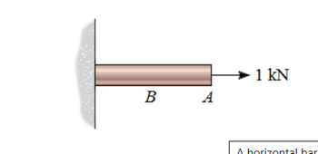
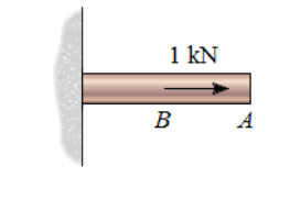
A horizontal bar is attached to a wall. When a force of 1 kN is applied at point A (figure 1) , the deflection at point A is δAA = 0.37 mm . When a 1 kN force is applied at point B (Figure 2), the deflection at point A is δAB = 0.2 mm .
A) What is the change in the length of the bar if there is a single load of 5.2 kN applied to the right at point A?
B) What is the change in the length of the bar if a load of 3.4 kN is applied to the left at A and a load of 10.4 kN is applied to the right at B?
C) If a load of 5.2 kN is applied to the right at point B, then what load magnitude must be applied to the left at point A to make the length of the bar remain unchanged?


Trending nowThis is a popular solution!
Step by stepSolved in 6 steps with 5 images

- The frame shown in Figure 3.1 has internal pins at points B, C and D and is supported by a pin at point A and a roller at point E. The loading consists of two concentrated loads and a point moment, as shown in the figure. a) Calculate the support reactions at points A and E. A 6 in. B -9 -9 in. →✦9 in. →✦9 in. →| 500 lb 700 lb ←9 in. D E Figure 3.1 - Compound Frame 2 kip-in 12 in. 12 in.arrow_forwardA long, slender structural aluminum [E = 69 GPa] flanged shape is used as a L = 9.2-m-long column. The column is supported in the x direction at base A and pinned at ends A and C against translation in the y and z directions. Lateral support is provided to the column so that deflection in the x-z plane is restrained at mid-height B; however, the column is free to deflect in the x-y plane at B. Assume that b; = 102 mm, d = 122 mm, t; = 8 mm, and tw = 6 mm. Determine the maximum compressive load P the column can support if a factor of safety of 2.9 is required. In your analysis, consider the possibility that buckling could occur about either the strong axis (i.e., the z axis) or the weak axis (i.e., the y axis) of the aluminum column. P bf C d Lateral В bracing 2 Determine the moment of inertia with respect to the y and the z axes through the centroid of the cross section area. Answers: ly = i mm“, Iz = i mm4.arrow_forwardConsider the steel truss and member cross-section presented in figures below. All the members of the truss have the same cross-section as shown in the figure to the right. They all also have a Young's Modulus of 210 GPa. What can the highest value of force F be before member AC fails by buckling? Force 1AN - 300 mm 40° 4 m $35 mm 7m 300 mm 8 m 35 mm 35 mm 35 mm Please provide your answer in kN.arrow_forward
- A solid circular brass rod is subjected to a compressive axial load of P = 120 kN. The diameter of the rod is d = 30 mm, and its length is L = 1000 mm. After load P is applied, the contraction of the rod is ō = 36 mm, and its diameter becomes d' = 30.360 mm. What is the modulus of elasticity for this material? P L Parrow_forwardA load P is supported by a structure consisting of rigid bar ABC, two identical solid bronze [E = 14100 ksi] rods, and a solid steel [E = 28000 ksi] rod, as shown. The bronze rods (1) each have a diameter of 0.61 in. and they are symmetrically positioned relative to the center rod (2) and the applied load P. Steel rod (2) has a diameter of 0.47 in. Assume L₁-39 in and L2-72 in. If all bars are unstressed before the load P is applied, determine the normal stresses in bronze rods (1) and steel rod (2) after a load of P = 29 kips is applied. O (1) A Answers: 0₁ = i 0₂ = i L2 (2) B P ksi. ksi. Larrow_forward
 Elements Of ElectromagneticsMechanical EngineeringISBN:9780190698614Author:Sadiku, Matthew N. O.Publisher:Oxford University Press
 Mechanics of Materials (10th Edition)Mechanical EngineeringISBN:9780134319650Author:Russell C. HibbelerPublisher:PEARSON
 Thermodynamics: An Engineering ApproachMechanical EngineeringISBN:9781259822674Author:Yunus A. Cengel Dr., Michael A. BolesPublisher:McGraw-Hill Education
 Control Systems EngineeringMechanical EngineeringISBN:9781118170519Author:Norman S. NisePublisher:WILEY
 Mechanics of Materials (MindTap Course List)Mechanical EngineeringISBN:9781337093347Author:Barry J. Goodno, James M. GerePublisher:Cengage Learning
 Engineering Mechanics: StaticsMechanical EngineeringISBN:9781118807330Author:James L. Meriam, L. G. Kraige, J. N. BoltonPublisher:WILEY


