
Structural Analysis
6th Edition
ISBN: 9781337630931
Author: KASSIMALI, Aslam.
Publisher: Cengage,
expand_more
expand_more
format_list_bulleted
Related questions
Question
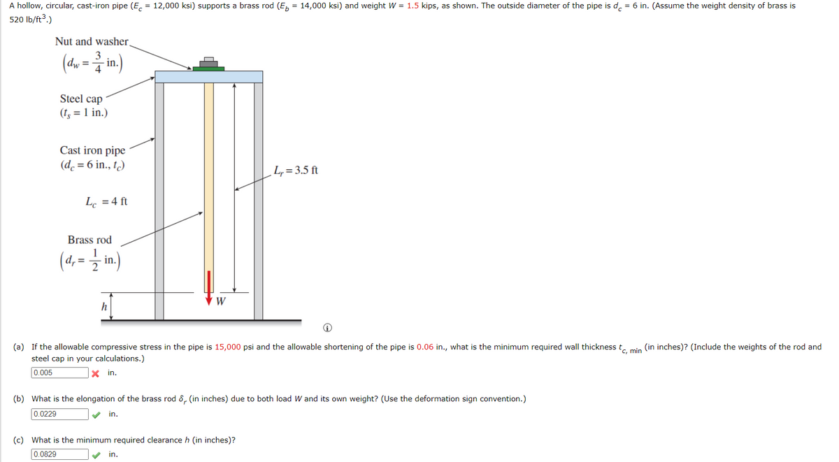

Transcribed Image Text:A hollow, circular, cast-iron pipe (E, = 12,000 ksi) supports a brass rod (E, = 14,000 ksi) and weight W = 1.5 kips, as shown. The outside diameter of the pipe is d, = 6 in. (Assume the weight density of brass is
520 Ib/ft3.)
%3D
Nut and washer.
(d, = in.)
3
%3D
4
Steel cap
(t, = 1 in.)
Cast iron pipe
(d. = 6 in., t.)
L,= 3.5 ft
L. =4 ft
Brass rod
(4,= in.)
W
h
(a) If the allowable compressive stress in the pipe is 15,000 psi and the allowable shortening of the pipe is 0.06 in., what is the minimum required wall thickness t. min (in inches)? (Include the weights of the rod and
steel cap in your calculations.)
0.005
X in.
(b) What is the elongation of the brass rod 8, (in inches) due to both load W and its own weight? (Use the deformation sign convention.)
0.0229
in.
(c) What is the minimum required clearance h (in inches)?
0.0829
in.
Expert Solution
This question has been solved!
Explore an expertly crafted, step-by-step solution for a thorough understanding of key concepts.

This is a popular solution

Trending nowThis is a popular solution!

Step by stepSolved in 3 steps with 3 images

Knowledge Booster


Learn more about
Need a deep-dive on the concept behind this application? Look no further. Learn more about this topic, civil-engineering and related others by exploring similar questions and additional content below.Similar questions
- UPVOTE WILL BE GIVEN. WRITE THE COMPLETE SOLUTIONS LEGIBLY. NO LONG EXPLANATION NEEDED. SOLVE IN 2 DECIMAL PLACES. BOX THE FINAL ANSWERS.arrow_forwardThe wood column is ixed at its base and free at its top. Determine the load P that can be applied to the edge of the column without causing the column to fail either by buckling or by yielding. Ew = 12 GPa, sY = 55 MPa.arrow_forward1- Calculate maximum deflection of the beams. 2- Check the suitability of the section assuming the code limitation of L/240. 3- If maximum deflection doesn’t meet the code requirement, propose your solution. Steel: Section properties: I=366,000,000 mm4, E=2*(10)5 N/mm2arrow_forward
- Problem 3 (20 minutes) The bars' assembly has the dimensions, diameters and materials indicated (EST 29,000 ksi; EBR = 15,000 ksi). The assembly is fixed at one end and has D in, E = 1. 10 in and F20 kip. Determine the normal force N in the bronze and the steel = d=2in = 30 d= 1 in F(kip) BRONZE ← STEEL A B ↑ c D(in) Elin 2. Draw the normal force diagram along the assembly 3. Determine the elongations ALAB (of portion AB), ALBC (of portion BC) and ALACarrow_forwardThe prismatic rod shown is made of a steel that is assumed to be elastoplastic with E = 200 GPa and oy = 280 MPa. Knowing that couples M and M' of moment 525 N·m are applied and main- tained about axes parallel to the y axis, determine (a) the thick- ness of the elastic core, (b) the radius of curvature of the bar. y M 18 mm 24 mm X 'M'arrow_forwardA compound bar consisting of bronze, aluminum, and steel segments is loaded axially as shown in the figure. Determine the maximum allowable value of P if the change in length of the bar is limited to 2 mm and the working stresses prescribed in the table are not to be exceeded. E=200 GPa A=D300mm? L=3m 2m 2 m 3m 1.5m Match each tem to a choicearrow_forward
arrow_back_ios
arrow_forward_ios
Recommended textbooks for you
 Structural Analysis (10th Edition)Civil EngineeringISBN:9780134610672Author:Russell C. HibbelerPublisher:PEARSON
 Principles of Foundation Engineering (MindTap Cou...Civil EngineeringISBN:9781337705028Author:Braja M. Das, Nagaratnam SivakuganPublisher:Cengage Learning
 Fundamentals of Structural AnalysisCivil EngineeringISBN:9780073398006Author:Kenneth M. Leet Emeritus, Chia-Ming Uang, Joel LanningPublisher:McGraw-Hill Education
 Traffic and Highway EngineeringCivil EngineeringISBN:9781305156241Author:Garber, Nicholas J.Publisher:Cengage Learning
Structural Analysis (10th Edition)
Civil Engineering
ISBN:9780134610672
Author:Russell C. Hibbeler
Publisher:PEARSON
Principles of Foundation Engineering (MindTap Cou...
Civil Engineering
ISBN:9781337705028
Author:Braja M. Das, Nagaratnam Sivakugan
Publisher:Cengage Learning
Fundamentals of Structural Analysis
Civil Engineering
ISBN:9780073398006
Author:Kenneth M. Leet Emeritus, Chia-Ming Uang, Joel Lanning
Publisher:McGraw-Hill Education
Traffic and Highway Engineering
Civil Engineering
ISBN:9781305156241
Author:Garber, Nicholas J.
Publisher:Cengage Learning