Power System Analysis and Design (MindTap Course List)
6th Edition
ISBN: 9781305632134
Author: J. Duncan Glover, Thomas Overbye, Mulukutla S. Sarma
Publisher: Cengage Learning
expand_more
expand_more
format_list_bulleted
Question

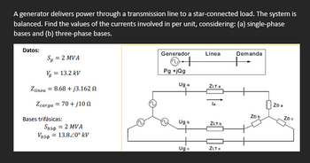
Transcribed Image Text:A generator delivers power through a transmission line to a star-connected load. The system is
balanced. Find the values of the currents involved in per unit, considering: (a) single-phase
bases and (b) three-phase bases.
Datos:
S₁ = 2 MVA
Vg
= 13.2 kV
Generador
++
Linea
Demanda
Pg+jQg
Uga
ZLT a
Zlinea 8.68+j3.162
Zcarga = 70+/10
la
ZDa
ZD b
ZD€
Bases trifásicas:
Ug b
ZLT b
Sb36 = 2 MVA
Vb34 = 13.820° kV
Ugo
ZLTC
Expert Solution
This question has been solved!
Explore an expertly crafted, step-by-step solution for a thorough understanding of key concepts.
Step by stepSolved in 2 steps with 5 images

Knowledge Booster
Similar questions
- The instantaneous power absorbed by the load in a single-phase ac circuit, for a general R LC load under sinusoidal-steady-state excitation. is (a) Nonzero constant (b) Zero (c) Containing double-frequency componentsarrow_forwardWhile the instantaneous electric power delivered by a single-phase generator under balanced steady-state conditions is a function of time havi ng two components of a constant and a double-frequency sinusoid, the total instantaneous electric power delivered by a three-phase generator under balanced steady-state conditions is a constant. (a) True (b) Falsearrow_forwardQ2) A 13.2-kV single-phase generator supplies power to a load through a transmission line. The load's impedance is Ztoad 500 236.87° ohm , and the transmission line's impedance is Zine = 60 253.1° ohm. To reduce transmission line losses to 0.0103 of its losses without using the transformers design and use two transformers T1 between the generator and the transmission line and T2 between the transmission line and the load.arrow_forward
- Q2) A 13.2-kV single-phase generator supplies power to a load through a transmission line. The load's impedance is Zload = 500 236.87° ohm, and the transmission line's impedance is Zline = 60 253.1° ohm. To reduce transmission line losses to 0.0103 of its losses without using the transformers design and use two transformers T1 between the generator and the transmission line and T2 between the transmission line and the load.arrow_forwardtwo generators supplying a load. Generator I has a no-load frequency of 62.5 Hz and a slope Sp1 of I MW/Hz. Generator 2 has a no-load frequency of 62.0 Hz and a slope sp2 of I MW/Hz. The two generators are supplying a real load totaling 2.5 MW at 0.8 PF lagging. (a) At what frequency is this system operating, and how much power is supplied by each of the two generators? (b) Suppose an additional I-MW load were attached to this power system. What would the new system frequency be, and how much power would Gl and G2 supply now? Generator 1 VT V2 Generator 2 VTí KVAR KVARarrow_forwardThe one-line diagram of a three-phase power system is shown in the above figure. The line impedances are in per- unit on a 100-MVA base, and the line admittances are neglected. Use Gauss-Seidel method in Matlab to analyze the system the tolerance of error is 10-3. Then anwser the questions as follows. V, = 1.05200 0.01+ j0.025 300 + j200 MVA 0.015 + j0.035 150 MW 200 +j150 MVA 0.01+ j0.03 |V = 1.03 The admittance matrix (Y_bus)? 0.02 + jo.04 0.0125 + jo.03 2.arrow_forward
- A three-phase balanced load of 15A per phase is supplied by a steel wire armoured cable with a c.s.a. of 2.5mm². The voltage drop for this cable is 15mv/A/m and the circuit is 40m long. Calculate the voltage drop in the cable.arrow_forwardelectrical engineering department plzz solvearrow_forwardA single-phase power system is shown as the equivalent circuit below. The system has a 480V generator connected to an ideal 1:10 step-up transformer (no losses), a transmission line, an ideal 20:1 step-down transformer and a load all in series as shown. The resistance of the transmission line is 20 S2 and the reactance j60 , a load is connected to the system with an impedance of 10/30° №. For the analysis of the system, use base values of 10 kVA and 480 V at the generator, find (a) per unit values of all impedances, (b) per unit current, (c) load power (W), (d) power loss (W). NG 480 20⁰ V 10 kVA Zone 1 1:10 20 Ω j60 Ω ZL Zone 2 20:1 ILoad Zone 3 ZLoad 10/30° Ωarrow_forward
- Two generators are supplying a load. Both the generators have a no-load frequency of61.5 Hz and the slope sp of 1 MW/HZ. If they are supplying a real load of 2.0 MW at 0.8 pflagging, what would be the system frequency and power sharing between two generators?What measures can be taken to make the frequency 60 HZ. If an additional 1.0 MW load isconnected to the existing one what would the system frequency be.arrow_forwardThe reactance of a generator is given as 0.25 per-unit based on the generator’s of 18 kV, 500 MVA. Find its per-unit reactance on a base of 20 kV, 100 MVA. a. 0.0505 b. 0.0605 c. 0.0405 d. 0.0606arrow_forwardIf, in one (360 degrees), all of the instantaneous power falls under positive loops (no negativeloops), the load must be:a. A resistorb. An inductor or capacitorExplain:arrow_forward
arrow_back_ios
SEE MORE QUESTIONS
arrow_forward_ios
Recommended textbooks for you
 Power System Analysis and Design (MindTap Course ...Electrical EngineeringISBN:9781305632134Author:J. Duncan Glover, Thomas Overbye, Mulukutla S. SarmaPublisher:Cengage Learning
 Delmar's Standard Textbook Of ElectricityElectrical EngineeringISBN:9781337900348Author:Stephen L. HermanPublisher:Cengage Learning

Power System Analysis and Design (MindTap Course ...
Electrical Engineering
ISBN:9781305632134
Author:J. Duncan Glover, Thomas Overbye, Mulukutla S. Sarma
Publisher:Cengage Learning

Delmar's Standard Textbook Of Electricity
Electrical Engineering
ISBN:9781337900348
Author:Stephen L. Herman
Publisher:Cengage Learning