Question
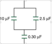
(a) Find the total capacitance of the combination of capacitors in Figure 19.33.
(b) If there is a potential of 425.0V across the capacitor circuit, what is the total charge of the capacitor circuit?

Transcribed Image Text:W physics question
Q. Search in Document
Home
Insert
Design
Layout
References
Mailings
Review
View
Picture Format
+ Share
Calibri (Body)
12
A- A-
E- E - E - E
AaBbCcDc AaBbCcDdEe AaBbC AaBbCcDdEe AaBbCcDdEe
AaBbCcDdEe
AaBbCcDdEe
AgBbCcDdEe
U - abe
X, x2
No Spacing
Paste
В
I
Heading 2
Styles
Pane
Normal
Heading 1
Title
Subtitle
Subtle Emp...
Emphasis
CH19 P57.
(a) Find the total capacitance of the combination of capacitors in Figure 19.33.
(b) If there is a potential of 425.0425.0V across the capacitor circuit, what is the total
charge of the capacitor circuit?
10 μF
2.5 µF
0.30 µF
Page 1 of 1
36 Words
English (US)
100%
Expert Solution
arrow_forward
Step 1
Given:
The diagram given is as follows:

Introduction:
Capacitance is the ratio of the amount of electric charge stored on a conductor to a difference in electric potential. The capacitor is a component that has the ability or “capacity” to store energy in the form of an electrical charge producing a potential difference across its plates, much like a small rechargeable battery.
Trending nowThis is a popular solution!
Step by stepSolved in 2 steps with 1 images

Knowledge Booster
Similar questions
- Two capacitors are connected in series between the terminals of a 20.0-V battery. If their capacitances are 35.0 µF and 46.0 µF, determine the following. (a) the equivalent capacitance of the system (b) the magnitude of charge stored on each plate of either capacitor (c) the voltage across the 35.0 µF capacitor (Give your answer to at least one decimal place.) (d) the voltage across the 46.0 µF capacitorarrow_forwardA 243-μF capacitor is connected in series with a 122-μF capacitor. What is the equivalent capacitance of the pair? Express your answer to three significant figures and include appropriate units.arrow_forwardA circuit contains a single 220-pF capacitor hooked across a battery. It is desired to store four times as much energy in a combination of two capacitors by adding a single capacitor to this one. What would its value be?arrow_forward
- If it is required to store 32.9 μC of electric charge in a capacitor in an electric circuit, what should the capacitance of the capacitor be if a voltage supply can apply 4.0 V of voltage to the capacitor? Report the number in the unit of μFarrow_forwardConsidering the circuit shown, if the emf of the battery is 6 V, the charge on the 4-pF capacitor is: 4 HF 2 F 3HF Select one: 8 µC 4 pC 12 μC 24 HCarrow_forwardFind the following. (In the figure, use C1 = 10.00 μF and C2 = 5.00 μF.) (a) the equivalent capacitance of the capacitors in the figure above ______μF (b) the charge on each capacitor on the right 10.00 μF capacitor _____μC on the left 10.00 μF capacitor _____μC on the 5.00 μF capacitor ______μC on the 6.00 μF capacitor ______μC (c) the potential difference across each capacitor on the right 10.00 μF capacitor _____V on the left 10.00 μF capacitor _____V on the 5.00 μF capacitor ______V on the 6.00 μF capacitor ______Varrow_forward
arrow_back_ios
arrow_forward_ios