Structural Analysis
6th Edition
ISBN: 9781337630931
Author: KASSIMALI, Aslam.
Publisher: Cengage,
expand_more
expand_more
format_list_bulleted
Concept explainers
Question

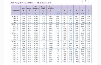
Transcribed Image Text:Wide-Flange Sections or W Shapes-U.S. Customary Units
Designation
W24 x 94
24 x 76
24 × 68
24 x 55
W21 x 68
21 x 62
21 x 50
21 x 44
W18 x 55
18 x 50
18 x 40
18 x 35
W16 x 57
16 x 50
16 x 40
16 x 31
W14 x 68
14 x 53
14 x 48
14 x 34
14 x 30
14 x 26
14 x 22
Area Depth
A
d
in.²
27.7
22.4
20.1
16.2
20.0
18.3
14.7
13.0
16.2
14.7
11.8
10.3
16.8
14.7
11.8
9.13
20.0
15.6
14.1
10.0
in.
24.3
23.9
23.7
23.6
21.1
21.0
20.8
20.7
18.1
18.0
17.9
17.7
16.4
16.3
16.0
15.9
14.0
13.9
13.8
14.0
8.85
13.8
7.69 13.9
6.49 13.7
Web
thickness
tw
in.
0.515
0.440
0.415
0.395
0.430
0.400
0.380
0.350
0.390
0.355
0.315
0.300
0.430
0.380
0.305
0.275
0.415
0.370
0.340
0.285
0.270
0.255
0.230
Flange Flange
width
thickness
bf
tf
in.
9.07
8.99
8.97
7.01
8.27
8.24
6.53
6.50
7.53
7.50
6.02
6.00
7.12
7.07
7.00
5.53
10.0
8.06
8.03
6.75
6.73
5.03
5.00
in.
0.875
0.680
0.585
0.505
0.685
0.615
0.535
0.450
0.630
0.570
0.525
0.425
0.715
0.630
0.505
0.440
0.720
0.660
0.595
0.455
0.385
0.420
0.335
Ix
in.4
2700
2100
1830
1350
1480
1330
984
843
890
800
612
510
758
659
518
375
722
541
484
340
291
245
199
Sx
in.³
222
176
154
114
140
127
94.5
81.6
98.3
88.9
68.4
57.6
92.2
81.0
64.7
47.2
103
77.8
70.2
48.6
42.0
35.3
29.0
in.
9.87
9.69
9.55
9.11
8.60
8.54
8.18
8.06
7.41
7.38
7.21
7.04
6.72
6.68
6.63
6.41
Iy
in.4
109
82.5
70.4
29.1
64.7
57.5
24.9
20.7
44.9
40.1
19.1
15.3
43.1
37.2
28.9
12.4
6.01 121
5.89
5.85
5.83
5.73
5.65
5.54
57.7
51.4
23.3
19.6
8.91
7.00
Sy
in.3
24.0
18.4
15.7
8.30
15.7
14.0
7.64
6.37
11.9
10.7
6.35
5.12
12.1
10.5
8.25
4.49
24.2
14.3
12.8
6.91
5.82
3.55
2.80
in.
1.98
1.92
1.87
1.34
1.80
1.77
1.30
1.26
1.67
1.65
1.27
1.22
1.60
1.59
1.57
1.17
2.46
1.92
1.91
1.53
1.49
1.08
1.04

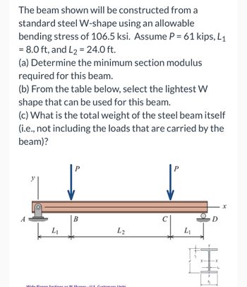
Transcribed Image Text:The beam shown will be constructed from a
standard steel W-shape using an allowable
bending stress of 106.5 ksi. Assume P = 61 kips, L₁
= 8.0 ft, and L₂ = 24.0 ft.
(a) Determine the minimum section modulus
required for this beam.
(b) From the table below, select the lightest W
shape that can be used for this beam.
(c) What is the total weight of the steel beam itself
(i.e., not including the loads that are carried by the
beam)?
A
L₁
B
L2
Wide-Flange Sections or W Shanes US Customary Units
P
L₁
bf
X
Expert Solution
This question has been solved!
Explore an expertly crafted, step-by-step solution for a thorough understanding of key concepts.
This is a popular solution
Trending nowThis is a popular solution!
Step by stepSolved in 6 steps with 8 images

Knowledge Booster
Learn more about
Need a deep-dive on the concept behind this application? Look no further. Learn more about this topic, civil-engineering and related others by exploring similar questions and additional content below.Similar questions
- Calcualte the following: Total factored floor load in 2 decimal places, ___ kPa Total factored uniform load on girder GH in 2 decimal places, ___ kN/m Maximum ultimate bending moment at discontinuous end of girder JK to the nearest whole number = ___ kN·marrow_forwardA simply supported beam, circular in cross section, of span L supports a point load W at mid span. The length of elastic-plastic zone at the plastic hinge will be A 0.33 L B 0.41 L C 0.50 L D 0.58 Larrow_forwardDetermine the maximum load that an 8 foot long 2"x4" rectangular aluminum alloy bar (E = 10.5x10^3ksi, σY = 40 ksi) can support with a factor of safety of 3 for both crushing and buckling if it has endconditions of:a. Pinned-pinned.b. Pinned-fixed.c. Fixed-free.d. Fixed-fixed.arrow_forward
arrow_back_ios
arrow_forward_ios
Recommended textbooks for you

 Structural Analysis (10th Edition)Civil EngineeringISBN:9780134610672Author:Russell C. HibbelerPublisher:PEARSON
 Principles of Foundation Engineering (MindTap Cou...Civil EngineeringISBN:9781337705028Author:Braja M. Das, Nagaratnam SivakuganPublisher:Cengage Learning
 Fundamentals of Structural AnalysisCivil EngineeringISBN:9780073398006Author:Kenneth M. Leet Emeritus, Chia-Ming Uang, Joel LanningPublisher:McGraw-Hill Education
 Traffic and Highway EngineeringCivil EngineeringISBN:9781305156241Author:Garber, Nicholas J.Publisher:Cengage Learning


Structural Analysis (10th Edition)
Civil Engineering
ISBN:9780134610672
Author:Russell C. Hibbeler
Publisher:PEARSON

Principles of Foundation Engineering (MindTap Cou...
Civil Engineering
ISBN:9781337705028
Author:Braja M. Das, Nagaratnam Sivakugan
Publisher:Cengage Learning

Fundamentals of Structural Analysis
Civil Engineering
ISBN:9780073398006
Author:Kenneth M. Leet Emeritus, Chia-Ming Uang, Joel Lanning
Publisher:McGraw-Hill Education


Traffic and Highway Engineering
Civil Engineering
ISBN:9781305156241
Author:Garber, Nicholas J.
Publisher:Cengage Learning