Introductory Circuit Analysis (13th Edition)
13th Edition
ISBN: 9780133923605
Author: Robert L. Boylestad
Publisher: PEARSON
expand_more
expand_more
format_list_bulleted
Concept explainers
Question

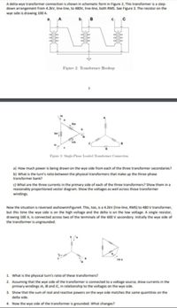
Transcribed Image Text:A deita wye transformer connection is shown in schematic form in Figure 2, This transformer is a step-
down arrangement from 4.2kV, line-line, to 480V, line-ine, both RMS. See Figure 3. The resistor on the
wye side is drawing 100 A.
b
Figure 2 Transformer Hookup
iba
b.
lac
Fizune 3: Single-Phve Loaded Trafoer Connecetion
a) How much power is being drawn on the wye side from each of the three transformer secondaries?
b) What is the turn's ratio between the physical transformers that make up the three-phase
transformer bank?
c) What are the three currents in the primary side of each of the three transformers? Show them in a
reasonably proportioned vector diagram. Show the voltages as well across those transformer
windings.
Now the situation is reversed asshowninFigure4. This, too, is a 4.2kV (line-line, RMS) to 480 V transformer,
but this time the wye side is on the high voltage and the delta is on the low voltage. A single resistor,
drawing 100 A, is connected across two of the terminals of the 600 V secondary. Initially the wye side of
the transformer is ungrounded.
1 What is the physical turn's ratio of these transformers?
2. Assuming that the wye side of the transformer is connected to a voltage source, draw currents in the
primary windings IA, IB and iC, in relationship to the voltages on the wye side.
3. Show that the sum of real and reactive powers on the wye side matches the same quantities on the
delta side.
4. Now the wye side of the transformer is grounded. What changes?
rele
ele
ele
Expert Solution
This question has been solved!
Explore an expertly crafted, step-by-step solution for a thorough understanding of key concepts.
This is a popular solution
Trending nowThis is a popular solution!
Step by stepSolved in 4 steps with 1 images

Knowledge Booster
Learn more about
Need a deep-dive on the concept behind this application? Look no further. Learn more about this topic, electrical-engineering and related others by exploring similar questions and additional content below.Similar questions
- 6. For the air core transformer circuit shown below, determine the currents la and lb in the direction shown. Express each answer in polar form. R1-302 www la ZI1=150 E=10/0 M=j20 Ze= n Z12=j62 lb R2=50 la Ibarrow_forwardThree single phase transformers are connected in a Delta-Wye configuration. Each transformer is rated 13kV/64kV. The transformers are connected to a 3 phase 13kV (L-L) supply and the balanced three phase load is 788KVA. What is the current magnitude in the secondary winding of each transformer? explain the steps too pleasearrow_forwardExcercies: 1. Two transformers A and R to a load of (2+jh5) Their impedanas in secondary terms Coltjo.6)5r EA = 200 Lov output and Power factor of each transformer are Connected in parallel ZA = (o15t+j 0.8)2 and zR= Their noload termind nltages are and Es = 21010V Fnd the poer are %3D 11 2. Two trans formes A andB of ratings 500KVA and 25okVA supplying a load kVA of 750 at a8 Pf lagging. Their open circuit voltayes are 400V and 410V respecctively. Transformer A has 1% rsistance and 5/ reactance and transformer B hay s resistance and 4 reactance. Fnd (a) Cross-curnt in the seondaries load shared by each transforcmer. are on no-load,b) the 2.arrow_forward
arrow_back_ios
arrow_forward_ios
Recommended textbooks for you
 Introductory Circuit Analysis (13th Edition)Electrical EngineeringISBN:9780133923605Author:Robert L. BoylestadPublisher:PEARSON
 Delmar's Standard Textbook Of ElectricityElectrical EngineeringISBN:9781337900348Author:Stephen L. HermanPublisher:Cengage Learning
 Programmable Logic ControllersElectrical EngineeringISBN:9780073373843Author:Frank D. PetruzellaPublisher:McGraw-Hill Education
 Fundamentals of Electric CircuitsElectrical EngineeringISBN:9780078028229Author:Charles K Alexander, Matthew SadikuPublisher:McGraw-Hill Education
 Electric Circuits. (11th Edition)Electrical EngineeringISBN:9780134746968Author:James W. Nilsson, Susan RiedelPublisher:PEARSON
 Engineering ElectromagneticsElectrical EngineeringISBN:9780078028151Author:Hayt, William H. (william Hart), Jr, BUCK, John A.Publisher:Mcgraw-hill Education,

Introductory Circuit Analysis (13th Edition)
Electrical Engineering
ISBN:9780133923605
Author:Robert L. Boylestad
Publisher:PEARSON

Delmar's Standard Textbook Of Electricity
Electrical Engineering
ISBN:9781337900348
Author:Stephen L. Herman
Publisher:Cengage Learning

Programmable Logic Controllers
Electrical Engineering
ISBN:9780073373843
Author:Frank D. Petruzella
Publisher:McGraw-Hill Education

Fundamentals of Electric Circuits
Electrical Engineering
ISBN:9780078028229
Author:Charles K Alexander, Matthew Sadiku
Publisher:McGraw-Hill Education

Electric Circuits. (11th Edition)
Electrical Engineering
ISBN:9780134746968
Author:James W. Nilsson, Susan Riedel
Publisher:PEARSON

Engineering Electromagnetics
Electrical Engineering
ISBN:9780078028151
Author:Hayt, William H. (william Hart), Jr, BUCK, John A.
Publisher:Mcgraw-hill Education,