Structural Analysis
6th Edition
ISBN: 9781337630931
Author: KASSIMALI, Aslam.
Publisher: Cengage,
expand_more
expand_more
format_list_bulleted
Concept explainers
Question
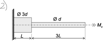
A cylindrical pin made of carbon steel is loaded with a maximum possible twisting moment Mv. Maximum allowed
shear stress is τmax = 40 MPa. The pin has the diameter measurement d = 50 mm, and the length measurement L = 250 mm.
Calculate the free end distortion θ in degrees. G=80 GPa

Transcribed Image Text:Ø3d
Ød
3L
-->> M
Expert Solution
This question has been solved!
Explore an expertly crafted, step-by-step solution for a thorough understanding of key concepts.
This is a popular solution
Trending nowThis is a popular solution!
Step by stepSolved in 4 steps with 3 images

Knowledge Booster
Learn more about
Need a deep-dive on the concept behind this application? Look no further. Learn more about this topic, civil-engineering and related others by exploring similar questions and additional content below.Similar questions
- W A L A Test beam Strain gauge (a) Unsymmetrical cantilever beam with weight applied at the free end and at the "shear centre", so that there is no torsion induced. b Section A-A Strain gauge 1 Strain gauge 3 Strain gauge 2 B (b) Location of Huggenberger strain gauges a D Referring to the above figure, calculate the location of the centroid, the second moments and product of area for the cross-section if; • D = 67 mm • B = 41 mm • t = 2.41 mm. From these, calculate the position and orientation of neutral axis for pure bending in the vertical plane (i.e. bending about a horizontal axis). Also calculate the directions of the principal second moments of area. Next, graph as scale diagram of the cross-section and plot the neutral axis on that diagram in the correct location and indicate the direction of deflection for the same conditionsarrow_forwardBY THE WAY P=66 KNarrow_forwardhow can i solve this one pleasearrow_forward
- Two solid cylindrical rods AB and BC are welded together at B and loaded as shown. Knowing that di =50 mm and d2 =30 mm, find the average normal stress at the midsection of (a) rod AB (b) rod BC A 300 mm -d, В 5OKN 150 mm 30KNarrow_forwardPart 2,3,4arrow_forward50 MPа A 35 MPa B 30 90 MPa The state of stress at a point in a member is shown on the element. You are required to determine the normal stress and shear stress acting on the inclined plane AB and show the result on the sectioned element: Using the method of equilibrium, and NOTE: support your answer with sketches and the FBD.arrow_forward
- .arrow_forwardThe solid shaft is fixed to the support at C and subjected to the torsional loadings shown. Determine the shear stress at points A in MPa. Let T2 =15 Nm and T1 = 8 kNm. Note: round off your answer to whole number T2 75 mm 75 mm 50 mm T1arrow_forwardA steel pipe is subjected to the 16-kN load shown below. Its outside diameter is 140 mm and its thickness is 7 mm. Consider that the yield strength of steel is 240 MPa. Analyze point H ONLY. Due to the pressure in the pipe, there is an 11.25-MPa (T) normal stress along x and a 22.50-MPa (T) normal stress along z of point H. A. Determine the internal forces and moments at the pertinent section through an FBD. B. Determine the stresses experienced by point H. Illustrate using a stress element. C. Determine the FS by MSST at point H D. Determine the von Mises equivalent stress at point H E. Determine the FS by MDET at point H 700 mm 16 KN 1,300 mmarrow_forward
- Solve it correctly please. I will rate accordingly.arrow_forwardThe shaft AB is formed by bonding steel tube and a brass core. Outer diameter of the steel tube is 60 mm and the diameter of the brass core is 30 mm. The shaft is subjected to uniform distributed torque o t kNm/m. The allowable shear stresses for steel and brass are (Tsteel)all = 80 MPa and (Tbrass)all = 50 MPa, respectively. Determine a) the maximum value of the uniform torque t , b) the corresponding angle of twist at A. (The shear modulus for steel and brass are Gsteel = 77 GPa and Gbrass = 40 GPa, respectively) - Steel Tube A t kNm/m B 30 mm 15 mm 1 m 1 m Brass Core Cross Sectionarrow_forwardThe hollow circular beam is fixed to the wall (with a bracket) on the left and has an end-cap on the right. The cross-section is shown. (a) Determine state of stress at point A & draw the stress element (b) Determine state of stress at point B & draw the stress element A 100 k-in Tout 2 in n=1.75 in В. B 40 k-in C Tout 30 k Xarrow_forward
arrow_back_ios
arrow_forward_ios
Recommended textbooks for you

 Structural Analysis (10th Edition)Civil EngineeringISBN:9780134610672Author:Russell C. HibbelerPublisher:PEARSON
 Principles of Foundation Engineering (MindTap Cou...Civil EngineeringISBN:9781337705028Author:Braja M. Das, Nagaratnam SivakuganPublisher:Cengage Learning
 Fundamentals of Structural AnalysisCivil EngineeringISBN:9780073398006Author:Kenneth M. Leet Emeritus, Chia-Ming Uang, Joel LanningPublisher:McGraw-Hill Education
 Traffic and Highway EngineeringCivil EngineeringISBN:9781305156241Author:Garber, Nicholas J.Publisher:Cengage Learning


Structural Analysis (10th Edition)
Civil Engineering
ISBN:9780134610672
Author:Russell C. Hibbeler
Publisher:PEARSON

Principles of Foundation Engineering (MindTap Cou...
Civil Engineering
ISBN:9781337705028
Author:Braja M. Das, Nagaratnam Sivakugan
Publisher:Cengage Learning

Fundamentals of Structural Analysis
Civil Engineering
ISBN:9780073398006
Author:Kenneth M. Leet Emeritus, Chia-Ming Uang, Joel Lanning
Publisher:McGraw-Hill Education


Traffic and Highway Engineering
Civil Engineering
ISBN:9781305156241
Author:Garber, Nicholas J.
Publisher:Cengage Learning