Elements Of Electromagnetics
7th Edition
ISBN: 9780190698614
Author: Sadiku, Matthew N. O.
Publisher: Oxford University Press
expand_more
expand_more
format_list_bulleted
Question
thumb_up100%
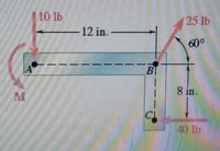
A couple of magnitude M = 80 lb·in. and the three forces shown are applied to an angle bracket. (a) Find the resultant of this system of forces. (b) Locate the points where the line of action of the resultant intersects line AB and line BC.

Transcribed Image Text:### Diagram Description for Educational Purposes
This diagram depicts a beam subjected to various forces and moments, commonly seen in structural analysis and physics problems. Below are details of the forces and distances:
- **Moments and Forces:**
- A counterclockwise moment, labeled "M," is applied at point A.
- A horizontal force of 10 lbs acts to the left at point A.
- A force of 25 lbs is applied at point B, directed at a 60-degree angle from the horizontal.
- **Dimensions:**
- The beam is 12 inches long between points A and B.
- There is a vertical segment dropping from point B to point C, measuring 8 inches in height.
- **Additional Forces:**
- At point C, a horizontal force of 40 lbs acts to the right.
The beam is analyzed under the influence of the applied forces and moment to determine the resultant forces, reactions, and bending moments at critical points. This type of diagram is essential for understanding the effects of forces in two-dimensional structures for engineering and physics applications.
Expert Solution
This question has been solved!
Explore an expertly crafted, step-by-step solution for a thorough understanding of key concepts.
This is a popular solution
Trending nowThis is a popular solution!
Step by stepSolved in 3 steps with 3 images

Knowledge Booster
Similar questions
- Given the system of forces shown below, Determine the following:(a) Moment of the 361-lb force about Point ‘B’(b) Moment of the 1,414-lb force about Point ‘A’(c) Moment of the 224-lb force about Point ‘C’(d) Resultant of the force system (Magnitude and Direction)(e) Moment of all the forces about Point ‘O’(f) Locate the ‘x’ and ‘y’ intercept using point ‘O’ as the referencearrow_forward4. The force F is acting along DC. Using the triple scalar product to determine the moment of F about the bar BA, you could use any of the following position vectors except a. Bс b. TAD AC DB BD C. d. e. 1.5 m 2 m C 0.5 m B 1m 2.5 m 4 marrow_forward
Recommended textbooks for you
 Elements Of ElectromagneticsMechanical EngineeringISBN:9780190698614Author:Sadiku, Matthew N. O.Publisher:Oxford University Press
 Mechanics of Materials (10th Edition)Mechanical EngineeringISBN:9780134319650Author:Russell C. HibbelerPublisher:PEARSON
 Thermodynamics: An Engineering ApproachMechanical EngineeringISBN:9781259822674Author:Yunus A. Cengel Dr., Michael A. BolesPublisher:McGraw-Hill Education
 Control Systems EngineeringMechanical EngineeringISBN:9781118170519Author:Norman S. NisePublisher:WILEY
 Mechanics of Materials (MindTap Course List)Mechanical EngineeringISBN:9781337093347Author:Barry J. Goodno, James M. GerePublisher:Cengage Learning
 Engineering Mechanics: StaticsMechanical EngineeringISBN:9781118807330Author:James L. Meriam, L. G. Kraige, J. N. BoltonPublisher:WILEY

Elements Of Electromagnetics
Mechanical Engineering
ISBN:9780190698614
Author:Sadiku, Matthew N. O.
Publisher:Oxford University Press

Mechanics of Materials (10th Edition)
Mechanical Engineering
ISBN:9780134319650
Author:Russell C. Hibbeler
Publisher:PEARSON

Thermodynamics: An Engineering Approach
Mechanical Engineering
ISBN:9781259822674
Author:Yunus A. Cengel Dr., Michael A. Boles
Publisher:McGraw-Hill Education

Control Systems Engineering
Mechanical Engineering
ISBN:9781118170519
Author:Norman S. Nise
Publisher:WILEY

Mechanics of Materials (MindTap Course List)
Mechanical Engineering
ISBN:9781337093347
Author:Barry J. Goodno, James M. Gere
Publisher:Cengage Learning

Engineering Mechanics: Statics
Mechanical Engineering
ISBN:9781118807330
Author:James L. Meriam, L. G. Kraige, J. N. Bolton
Publisher:WILEY